Vacuum furnaces are available in numerous styles and sizes and come in both standard and custom configurations. They are designed to process an almost limitless number of both semi-finished component parts as well as raw materials using a diverse set of thermal processes in equipment available from a wide variety of different equipment manufacturers located around the world.
The intent here is to provide a brief overview of some of the more common designs and applications found throughout the heat-treatment industry. The hope is that the reader will come away with an understanding that there is a vacuum furnace solution to virtually any design, application or specification encountered.
Why Vacuum?
Historically, vacuum heat-treating applications were classified in one of four areas, namely processes that could be:
- Performed using no technology other than vacuum
- Done better in a vacuum from a metallurgical perspective
- Done better in a vacuum from an economic standpoint
- Done better in a vacuum from a surface enhancement perspective
Today, given the demands for productivity and flexibility vacuum heat-treatment has been the preferred choice by the heat-treat industry. This is due to a number of reasons, not the least of which is that the technology (and hence the end result of the heat treatment process) now rests in the machine and not with the individual operating it. The drivers for vacuum technology are:
- Process control (i.e., accuracy)
- Process repeatability,
- Up-time reliability
- Adaptability to new materials, new processes, and new recipes
- Integration with manufacturing
- Reduced environmental impact.
All of these factors have resulted in a strong economic advantage for vacuum processing driven by higher productivity, less distortion and decreased cycle times.
Vacuum Furnace Design
The main components of a vacuum furnace (Fig. 1) include, but are often not limited to, the following subsystems:
- Vacuum vessel (aka shell)
- Hot zone
- Pumping system
- Cooling system
- Control system (temperature & vacuum)
- Handling system
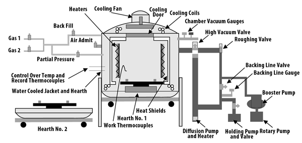
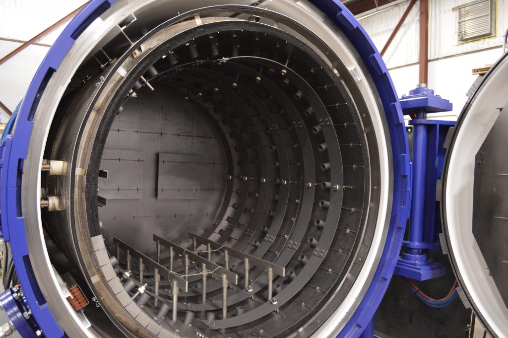
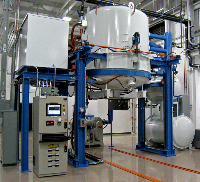
Vacuum furnaces available from most manufacturers are either horizontal (Fig. 2) or vertical (Fig. 3) configurations. While vacuum vessels need not be cylindrical in shape, most are round for purposes of strength and the fact that the annular spacing between the inner and outer shell provides a path for cooling water flow. Some (primarily older) vessels are square while others have cylindrical inner vessels in a square outer vessel, which houses the cooling water.
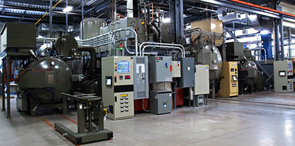
Vacuum furnaces are either batch style or continuous (aka semi-continuous types). The latter can be dual or multi-chamber designs or pusher styles. In batch style vacuum furnaces (Fig. 4) the workload is stationary throughout the cycle. In continuous style vacuum furnaces (Fig. 5) the workload moves from position to position.
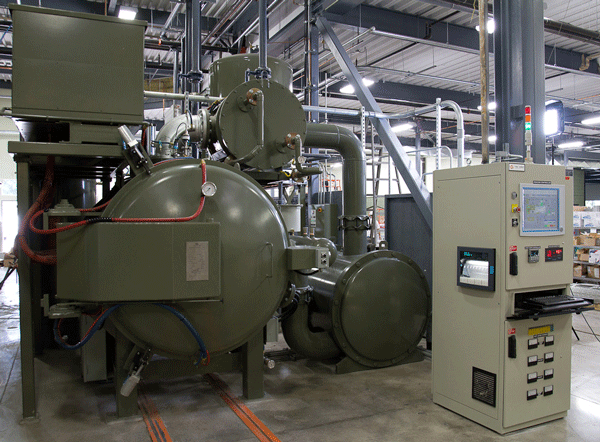
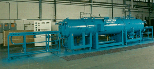
Vacuum furnaces can be what is commonly referred to in the industry as hot wall designs (Fig. 6), which are generally considered to be less expensive to manufacture. Hot wall vacuum furnaces equipped with retorts offer faster pump-down rates and typically fewer vacuum leak problems.
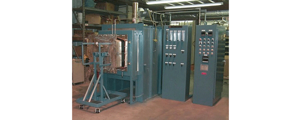
More common today are cold wall designs (Fig. 7), which have higher operating temperature capabilities with 1315°C (2400°F) often standard and 1650°C (3000°F) or higher optional. These furnaces have fast heating and cooling performance, superior temperature uniformity (over retort designs) and lower heat losses and less heat load released to the surroundings.
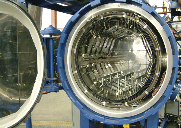
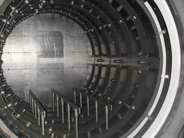
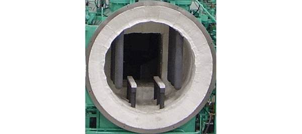
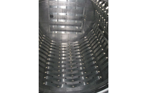
While there are many choices for the construction of the hot zone, the most popular choices are:
- All metallic elements and radiation shields (Fig. 8) including:
- Stainless steel or nickel-based having a maximum operating temperature of 1150°C (2100°F)
- Molybdenum having a maximum operating temperature of 1700°C (3100°F)
- Tungsten or tantalum having a maximum operating temperature of 2400°C (4350°F)
- All graphite hot zones with either graphite board, graphite felt, graphoil®, carbon-carbon composite material (Fig. 9)
- All ceramic fiber hot zones for hot wall designs (Fig. 10)
- Combination hot zones of metal, graphite and/or ceramic fiber with various heating element materials (Fig. 11)
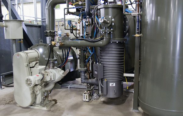
The choice of the pumping system (Fig. 12) is often application dependent and there are a number of different vacuum pump manufacturers. Often equipment suppliers have preferred vendors (which depending on location may influence pump choice). If certain features are necessary or important (for example, pumping speed under humid conditions) the user must convey these requirements to the manufacturer. Some of the factors to consider include:
- Volume and surface area of the vessel
- The time required for evacuation down to the final pressure
- Type of furnace hot zone internals
- Anticipated outgassing of the workload and related fixturing
In some instances, furnaces after being evacuated are backfilled with a partial pressure (e.g., argon, helium, hydrogen, nitrogen) in which the process is performed (the hardening of stainless steel being an example where a partial pressure is used to minimize vaporization of chromium from the part surface). Other applications, such as metal injection molding, are run in a hydrogen partial pressure atmosphere (Fig. 13).
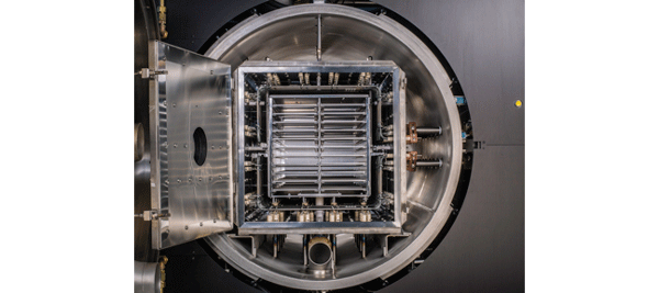
The size of the workload (Fig. Nos. 14 – 15) often dictates the style and to some extent, the features required on a vacuum furnace such as the processing temperature or quench type (oil or gas) and quench pressure needed to cool the workload.

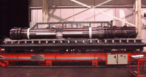
Vacuum furnaces run a number of metallurgical processes including:
- Annealing (e.g., copper heatsinks, nickel-based superalloy afterburner housings (Fig. 16) for jet fighters)
- Brazing (e.g., honeycomb brazing of combustion chamber jet engines)
- Case hardening
- Carbonitriding (e.g., die cutting punch edges)
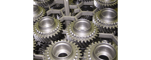
- Carburizing (Fig. 17) (e.g., aerospace and powertrain gears)
- Nitriding – gas, plasma (e.g. common rail fuel systems)
- Nitrocarburizing (e.g., steel regulator valves, seats and stems)
- Degassing (e.g., titanium logs)
- Homogenizing (e.g. titanium ingots)
- Metal injection molding (e.g., firearms)
- Nitriding (e.g., valve seats)
- Solution nitriding (e.g., 400 series stainless steel bearings)
- Hardening (e.g., aircraft landing gears (Fig. 18))
- Normalizing (e.g., automotive gear blanks)
- Sintering (e.g., automotive mirror mounts, anti-lock braking systems)
- Special processes (e.g., hydrizing and dehydrizing in titanium and tantalum powder production)
- Stress relief (e.g., aluminum bronze impellors for nuclear-powered attack submarines)
- Tempering (e.g., electrical switches, brass wire, beryllium copper wire)
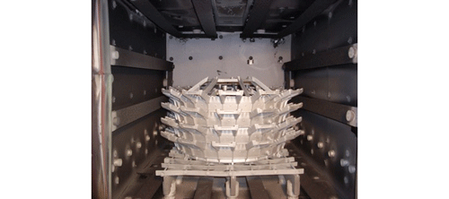
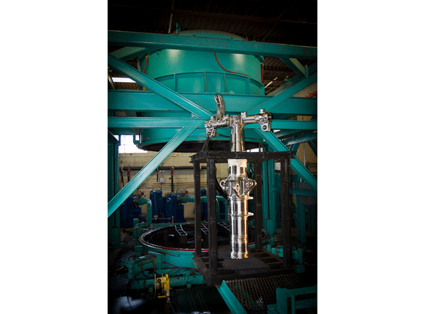
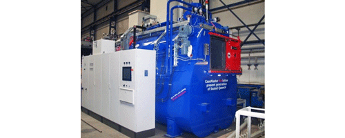
Vacuum furnaces are designed to quench loads in various types of cooling medium. Oil quenching (Fig. 19) remains popular using oils rated from ambient temperature to preheat oils at 50 – 80ºC (120 – 175ºF) and (less frequently) into hot oil up to 135 – 170ºC (275 – 340ºF). Gas quenching in sub-atmospheric to positive pressures of 2 – 25 bar pressure (Fig. 20) is even more commonplace. There is also some demand for units either having a combination of both oil and gas quenching (Fig. 21) or the capability of 2 – 5 bar pressure quenching over the surface of the oil.
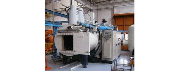

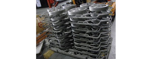
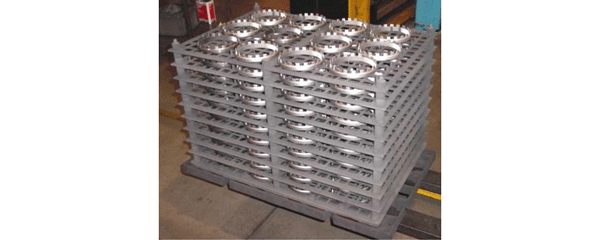
Vacuum furnaces can run a variety of loads and load configurations on alloy grids, in baskets and held in position by fixtures (Fig. 22). Alternative materials such as carbon/carbon composite fixtures (Fig. 23) are gaining in popularity as well.
Summary
Much more can and perhaps should be said about the various types of vacuum furnaces available to the marketplace. The key here is to provide to the reader an understanding that the diverse requirements of global manufacturing are being successfully met by use of standard and custom vacuum furnace designs similar or identical to the ones illustrated here.
References
1. Herring, Daniel H., Vacuum Heat Treatment (Volume I), BNP Media, 2012.
2. “The Vacuum Furnace Process” Application Note, Part No. HA029143 Issue 1, Eurotherm, 2005.
3. “Vacuum Furnace Types and Process Applications”, Industry Presentation, The HERRING GROUP, Inc., 2011.
