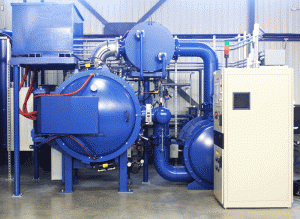
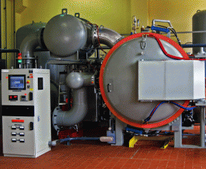
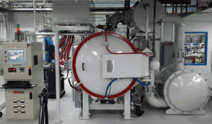
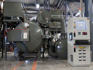
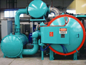
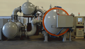
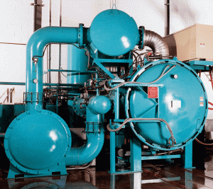
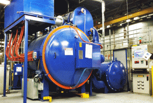
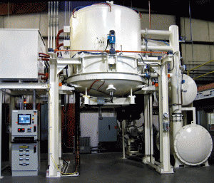
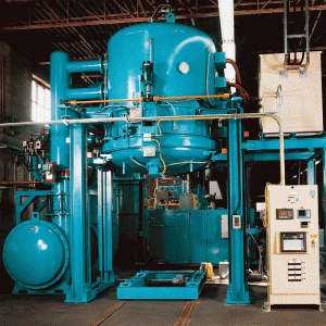
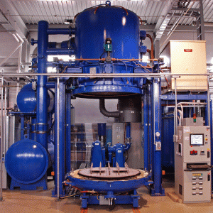
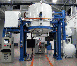
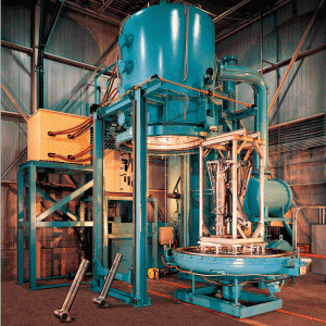
Premier Manufacturers of Advanced External Quench Vacuum Furnaces for Superior Processing.
VAC AERO is committed to building vacuum furnaces with the lowest cost of ownership achieved through superior design, top quality materials, and high-performance operation.
READ HUNDREDS OF TECHNICAL THERMAL PROCESSING PAPERS & ARTICLES
HORIZONTAL & VERTICAL VACUUM FURNACE SPECIFICATIONS (SEE BELOW)
VAC AERO designs and builds a wide range of vacuum heat treating furnaces, from small horizontal laboratory models to large vertical furnaces for diverse applications including vacuum heat treating and brazing (steels, superalloys, titanium), vacuum sintering (steels, titanium, advanced ceramics), hardening, tempering, annealing and a host of other special processes. With pressure ratings of 2 to 6 bar VAC AERO furnaces are used worldwide for diverse applications in aero-engine manufacturing, power generation, medical implants, commercial heat treating, tool and die, nuclear and other high-tech industries and are designed to meet any of our customers’ stringent requirements.
VAC AERO’s vacuum heat treat furnace design innovations are thoroughly tested in our own commercial heat treating facilities before being shipped to our customers. That means better quality, reliability, and efficiency to maximize uptime and productivity. VAC AERO’s experience, proven through decades of research into gas quenching and vacuum heat treating services in aerospace has provided us with valuable insight into the changing needs and rigorous demands of our furnace customers. As a result, VAC AERO has developed a keen understanding of the design and performance of vacuum furnace systems built to meet the most stringent requirements for reliability, productivity, and cost-efficiency.
VACUUM HEAT TREATING FURNACE SPECIFICATIONS
- Please click on the following links for a complete list of HORIZONTAL and VERTICAL furnace work zone sizes.
- Operating temperature range: 1000°F – 2400°F (538°C – 1316°C) for the entire range.
- Maximum clean-up temperature: 2450°F (1343°C) for 10 minutes maximum.
- Ultimate vacuum levels: 10-6 torr range in clean, leak-tight furnace.
- Temperature Uniformity: ± 10°F (6°C), equivalent to Class II of AMS 2750E in clean, empty furnace.
- High-performance external gas quenching for rapid cooling at positive pressures up to 15 psig.
- Minimized footprint to accommodate limited floor space or overhead clearance constraints.
- Fully automated and programmable, PC-based industrial controls package with remote access.
HOT ZONE:
Built for rugged usage and low maintenance, VAC AERO hot zones feature unitized construction for easy removal and maintenance. VAC AERO hot zones are designed with the following features:
- Heating Elements: Curved Graphite, Lanthanated Molybdenum (MoLa) Strip or Molybdenum Strip.
- Lightweight design’s low thermal mass enables faster quenching and longer life.
- Heavy duty hearth constructed with pure molybdenum pins, caps and rails.
- Insulation and heating elements mounted on a heavy-duty 14 ga. stainless steel support structure for superior longevity.
- Modular hot zone design with multiple heating zones and no moving parts to minimize maintenance and downtime.
- Modular ring assembly with multiple gas plenums that also act as a manifold to distribute high-velocity quenching gas uniformly throughout the workload.
- Nozzle configuration provides better gas penetration, improved gas velocity, and more uniform gas distribution throughout the load.
- Segmented curved graphite, molybdenum (or mola) elements for fast, easy repair and replacement.
- Thin, low mass element design for quick response during heating and cooling.
- Optional: Elements can be added to the front and back end shield assemblies (Horizontal) and top and bottom end shield assemblies (Vertical).
Need more info on our Hot Zones CLICK HERE
RADIATION SHIELDS:
Metal-Based Insulation Package: The heat shield package consists of one layer of 0.020” (0.5 mm) or 0.030” (0.8 mm) thick molybdenum (or lanthanated molybdenum) sheet backed by one layer of 0.010” (0.254 mm) thick molybdenum sheet and three layers of 0.014” (0.3556 mm) stainless steel sheet. The heat shield package is supported by a 14 ga. stainless steel assembly that also acts as a manifold to distribute the quenching gas uniformly throughout the workload.
Graphite-Based Insulation Package: The heat shield package consists of three layers of 1/2” (12mm) thick high purity graphite felt with an inner facing of graphite foil bonded carbon composite that provides added protection and enhanced reflectivity. The heat shield package is supported by a 14 ga. stainless steel assembly that also acts as a manifold to distribute the quenching gas uniformly throughout the workload. An optional extra layer of sacrificial graphite foil or carbon composite available.
VACUUM CHAMBER & DOOR:
Chamber Construction: The vacuum chamber and door are constructed of carbon steel (stainless steel optional). The chamber exterior is primed and painted the customer’s choice of color. The chamber inner wall is sealed with low-gassing epoxy paint and features a double-wall, water-cooled design with oversized water inlets and outlets assure maximum water flow. Water-cooled power terminals eliminate excessive heat on O-ring seals. The chamber is equipped with all necessary pumping ports, hot-zone power feedthroughs, and gas quench entries. The vacuum gauge ports and thermocouple jacks are conveniently located for easy access.
Vertical Furnace Tank Assembly: The furnace tank assembly, the ball screw assemblies, and the power supply are supported on a specially designed heavy-duty integrated steel structure. The tank assembly is vertically aligned with a motorized bottom opening head raised and lowered by four ball screws. Once lowered, the bottom head is rolled out from beneath the furnace by a powered drive to allow unobstructed loading and hot zone access. The drive is controlled by a remote station on the furnace support structure. The chamber is equipped with a hydraulically-powered breech-lock clamping system to secure the door during processing (2 bar and up).
Chamber Door – Horizontal Furnaces: The furnace door flanged and hinged on the side, and opens sufficiently to allow complete and unobstructed loading access to the hot zone. The chamber is equipped with a hydraulic powered breech-lock clamping system to secure the door during processing (2 bar and up).
Minimized Footprint – Horizontal Furnace: Minimized floor area footprint requirements are reduced by locating the hot zone power supply on a steel support structure above the vacuum chamber.
Workload Thermocouple Port: The The chamber is equipped with a water-cooled port and blanking flange. A workload thermocouple adapter plate, thermocouple plugs, and vacuum feedthrough seals for type K or N workload thermocouples as well as a heat protected junction strip located near the chamber opening for convenient thermocouple connection.
Optional: A manual or hydraulically powered load/unload dolly can be included.
VACUUM PUMPING SYSTEM:
Low Vacuum: The vacuum pump down is automatic and interlocked. When started, the roughing valve opens and pumps the system to about 40 Torr. The vacuum booster is then activated and the system pumps to an ultimate vacuum in the 10-3 Torr range. At 4 x 10⁻² Torr, the thermal process cycle is permitted to start but will hold if the pressure rises above 1 x 10⁻¹ Torr.
High Vacuum: The vacuum pumping sequence is automatic and interlocked. When pump down is initiated the roughing valve opens and evacuates the system to approximately 20 torr. The vacuum booster pump then begins pumping. At 8 x 10⁻² torr (80 microns), the roughing valve closes, then foreline and main valves are opened in proper sequence, and the system is evacuated to an ultimate vacuum in the 10-5 torr range. The VAC AERO design uses a holding pump to maintain a low pressure on the diffusion pump foreline at all times. This feature, combined with properly timed sequencing of vacuum valves, eliminates backstreaming of pump oils for most applications.
Roughing Pumps: Best of brand roughing and booster pumps. Optional: Oil mist separator
Diffusion Pumps: Best of brand 6, 10, 16, 20 or 35-inch diffusion pumps complete with cold cap, quick cool coil and charged with fluid.
Holding Pumps: Best of brand rotary vane pumps.
Vacuum & Holding Valves:
- 2 bar: Electro-pneumatic poppet valves, appropriately sized for optimal pumping system performance.
- 6 bar: Electro-pneumatic butterfly valves, appropriately sized for optimal pumping system performance.
GAS QUENCH SYSTEM – CS 4500/7500/10000/12000:
The furnace is equipped with an external recirculating inert gas quenching system rated at between 4500, 7500, 10,000 and 12,000 CFM. The gas quench system distributes high-velocity gas via modular plenums through circumferentially located internal nozzles located around the workload providing 360-degree quenching for better gas penetration, improved gas velocity and more uniform gas distribution throughout the load.
The gas quench system includes:
- 20 HP to 300 HP quench blower motor with soft start.
- Gas quench system can be designed for use with Nitrogen or Argon gas.
- Gas quenching system rated at between 4500 and 12,000 CFM
- High efficiency, long life, tube/fin heat exchanger.
- Quench blower powered by a soft-start electric motor.
- Selectable operating gas quench pressures from .85, 2, 4, 6 or 10 bar.
- Special High efficiency, long life, tube/fin heat exchanger.
- Welded steel quench piping, water-cooled where appropriate and vibration isolated.
Optional: Integrated dew point meter
Partial Pressure Operation: The furnace can be operated at partial pressures using either the inert gas nitrogen or argon. Optional: Hydrogen Partial Pressure Capability.
PROCESS CONTROL & CABINET
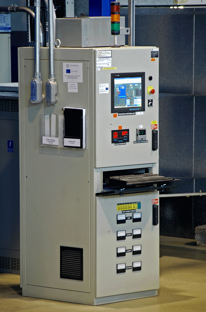
VAC AERO’s uses the Honeywell HC900 process controller integrated with the Honeywell Experion HS software running on a Windows 7-based PC to provide Supervisory Control and Data Acquisition (SCADA). The Honeywell HC900 controller can connect remote users to the system, link multiple furnaces together, or to other operating systems in a facility.
The VAC AERO control system is programmable, logic-based and comprised of proven hardware components, suitably hardened for an “industrial shop” environment. The software has been optimized to cover all normal operating and alarm conditions. VAC AERO’s design philosophy is to simplify control by using the program capabilities to perform as many functions as possible, thereby reducing operator dependence. The software is optimized to control the machine functions and furnace temperature and to cover all normal operations, maintenance alerts and alarm conditions.
VAC AERO control systems have been operating reliably through thousands of service hours. VAC AERO customers enjoy online technical support and unequaled performance from the HC900 Data Acquisition and Control System.
The system’s key benefits include:
- Digital trimming is used to obtain uniformity over the entire operating range.
- Compatible with plant-wide SCADA and network integration.
- Controls and instrumentation are housed in a ventilated control cabinet.
- Enhanced maintenance and troubleshooting management and trending.
- Extensive alarm and event management and reporting.
- Extensive range of standard displays is available.
- Operator sign-on/sign-off security provides multiple control levels to limit operator control of individual items of equipment.
- Process cycle validation.
- Temperature control using advanced algorithms, auto-tuning, multiple PID loops, and multiple zone digital trimming.
Need more info on our Control Systems CLICK HERE
UTILITIES REQUIREMENTS:
Electrical Power Supply: Furnace electrical requirements based on customer’s voltage. Amount of total power required based on furnace equipment details.
Water: Depending on individual specs the furnace system requires anywhere between a 50, 100 or 200 GPM water system at a pressure of 55 psig and a temperature of 80°F. The customer is responsible for ensuring water is suitably treated to prevent corrosion, mineral build-up and cooling system blockage due to particulate matter.
Air: 100 psig, 1/4″ NPT (constant supply required, even when the furnace is shut down).
Inert Gas: Nitrogen and Argon regulated at 120 or 200 psig. Approximate quench gas volume consumed in each (.85) backfill cycle is based on the specifications of each individual furnace.
WATER COOLING SYSTEM:
The furnace water system consists of compact manifolds containing all necessary pressure regulators, valves, pressure switches and flow regulators with supply and drain hoses and fittings.
Optional: VAC AERO can provide a Dual Loop Furnace Cooling System to supply coolant to the furnace. (see below)
GAS STORAGE SYSTEM
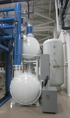
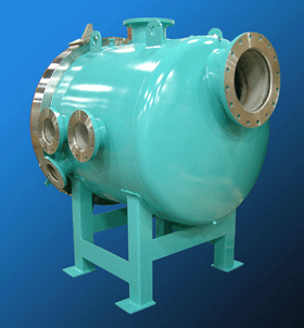
In vacuum furnace applications where rapid gas quenching is required (for example, heat treating of air hardening tool steels or high-speed steel) it is important that the furnace chamber is filled very rapidly with an inert gas. It is also important that this gas is supplied to the furnace without contamination. Discolored or contaminated parts are often the result of contaminated quench gas. The IG Gas Supply System built by VAC AERO is sized to rapidly fill the furnace chamber with quench gas. The system is designed to be supplied from high-pressure bulk gas storage or liquid storage source (cold converter) and includes backflow prevention, purge, and safety devices. The IG tank is an ASME approved vessel that can be supplied in vertical or horizontal configurations.
AFTERMARKET & FURNACE UPGRADE SERVICES
VAC AERO customers around the world enjoy online technical support and unparalleled performance from the most advanced vacuum furnace systems on the market.
VAC AERO offers aftermarket replacement parts, on-site furnace repair, inspection, and maintenance to keep your vacuum heat treating furnaces always up and running.
Vacuum furnace refurbishment increases its value, minimizes energy consumption and boosts performance. Customers with older VAC AERO furnaces often have their furnaces upgraded with the most current controls, instruments, new accessories or hardware. VAC AERO extends the life of your furnace and minimizes downtime by incorporating the improved performance features provided on new VAC AERO furnaces. VAC AERO will refurbish or upgrade your old furnace or any other brand of furnaces to help you keep up with the changing demands of your industry.
-
Furnace water cooling system Vacuum furnace maintenance and repairs.
- Hot Zone repairs, replacement, and retrofits.
- Control system upgrades, updates, and retrofits.
- Spare parts and materials.
OPTIONAL AUXILLIARY SYSTEMS:
VAC AERO supplies peripheral equipment to be used in conjunction with its furnace systems, including; IG Gas Storage/Supply Systems and Water Systems.
Inert Gas Quench Gas Storage/Supply Systems
VAC AERO’s IG tank is an ASME approved receiver, which at an internal gas pressure of 120 psig will supply a sufficient volume of quench gas to backfill the chamber to 2 bar in 30 seconds or less. The system is designed to be supplied from high-pressure bulk gas storage or liquid storage source (cold converter) and includes backflow prevention, as well as purge and safety devices. The IG tank can be supplied in vertical or horizontal configurations.
Dual Loop Furnace Water Cooling System
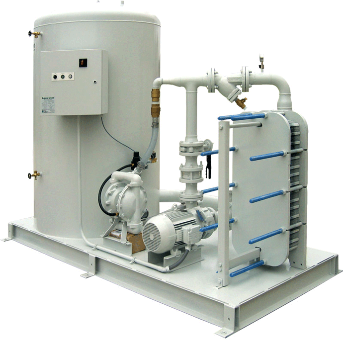
The Dual Loop furnace cooling system supplies coolant to the furnace. Rugged and virtually maintenance-free, the water system consists of a compact manifold containing all necessary pressure regulators, valves, pressure switches and flow regulators with supply and drain hoses and fittings. One side of the closed-loop system delivers treated coolant to the furnace. The other side raw water to remove heat from the furnace coolant through a plate/frame heat exchanger. The water system is available in several sizes with capacities designed to accommodate all furnaces.
The major components of the System consist of the following:
- Ready-to-install furnace cooling package with reservoir, pump, heat exchanger, valves and gauges mounted and connected to a single structural steel base. Optional air or natural gas-powered backup pumps are available.
- Remote Sump Package including reservoir, tower pump, valves, and gauges.
- Evaporative cooling tower with a corrosion-resistant shell.
- Electrical Control Package in NEMA 12 enclosure for the operation of the entire cooling system. Controls can be configured to operate with any available local power.
APPROVALS:
VAC AERO vacuum heat treating furnaces are built for complete safety during operation. All electrical components used in the fabrication of the furnace system are CSA (optional European CE standards) approved. All complete electrical assemblies will be inspected and approved by the Ontario Electrical Safety Authority:
The following codes are used as reference:
- Applicable NFPA standards
- AMS 2769 Vacuum Heat Treating (latest revision)
- AMS 2750E Pyrometry
- Applicable Occupational Safety & Health standards
The equipment is designed and constructed to meet National Fire Protection Association Standard 86D, the standards of the Occupational Safety and Health Association and the National Electrical Code as such are known by VAC AERO as of the purchase date. After installation at the customer site, each furnace is fully tested on-site for final customer approval and commissioning.
INSTALLATION, COMMISSIONING & TRAINING:
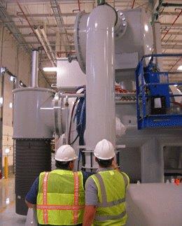
All our vacuum heat treating furnaces are shipped complete, tested and ready for installation. The customer is responsible for making all necessary site preparations and connecting power, water, inert gas, and compressed air supplies.
As part of every furnace contract, VAC AERO provides free pre-delivery training in heat treating processes, furnace operation, and maintenance. Commissioning activities include instrument configuration, verification of electrical, mechanical and thermal functions and performance testing consisting of a temperature uniformity survey and measuring of ultimate vacuum, leak up rate and pumping speed.
VAC AERO offers installation supervision or complete installation services in addition to the services provided in the commissioning package.
Installation Supervision: In addition to the services provided in the Commissioning package, VAC AERO can supply an experienced technician to supervise customer personnel during the installation of the furnace equipment. Installation supervision services are available for a fee.
Installation by VAC AERO: For an additional charge, VAC AERO can supply installation services.
Commissioning
After the vacuum heat treat furnace has been installed and connected by either VAC AERO or the customer, a qualified VAC AERO field engineer will visit the site for a period of up to 8-to10 days to commission the equipment and provide final onsite training. As part of every furnace contract, VAC AERO also provides pre-delivery training in heat treating processes, furnace operation, and maintenance. Commissioning activities include instrument configuration, verification of electrical, mechanical and thermal functions and performance testing consisting of a temperature uniformity survey and measuring of ultimate vacuum, leak up rate and pumping speed. If additional assistance is required beyond the 8-to10 days, it will be charged at a standard per diem rate plus all living expenses.
Operator Training
The customer is invited to send personnel for operational and maintenance training and installation instruction. Training for up to three customer personnel for three working days is provided at no charge. The customer is responsible for travel and living costs.
DOWNLOAD OUR HORIZONTAL VACUUM FURNACE BROCHURE
DOWNLOAD OUR VERTICAL VACUUM FURNACE BROCHURE
HUNDREDS OF ARTICLES WRITTEN BY WORLD RENOWN EXPERTS
Vacuum Heat Treating: Education & Training – VAC AERO International
Vacuum Technology with The Heat Treat Doctor with DAN HERRING
Vacuum Brazing with DAN KAY
Vacuum Pump Technology: Education and Training with DAN HERRING & HOWARD TRING
Metallography with GEORGE VANDER VOORT


