Vacaero

Manufacturers of heat treating and brazing vacuum furnaces and controls, complete hot zone and vacuum furnace retrofits, thermal spray coatings, plasma, HVOF and paint coating services.

VAC AERO Service Experience Trust
Canada FrançaisAccessibility |
  • Home
  • Company
  • Vacuum Furnaces
  • Thermal Processing
  • Coatings
  • Service & Support
  • Resources
  • Contact Us
  • Request for Quote

Metallography of Iron-Nickel Meteorites

June 5, 2018 by George Vander Voort

Metallography of Iron-Nickel Meteorites

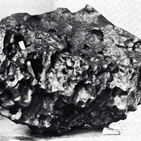
Meteorites have fascinated mankind for centuries. Indeed, more than two dozen meteorites have been venerated by Indian tribes, aborigines, Arabs and other ancient peoples. The study of meteorites is part of the overall study of the origin of our solar system. There was a recent meteor explosion over the city of Chelyabinsk with up to 1000 injuries. Think what the damage would have been like if it hit a major city. Some asteroids are exceptionally large, and when they strike earth, they can make an immense crater. Some of these, as in Figure 1, are in arid climates and can be seen today. Such an impact near the Yucatan Peninsula has been claimed to have caused the extinction of dinosaurs.

There are three basic types of meteorites: stones, stoney-irons, and iron. The classification of meteorites is a complex subject. For the iron meteorites, classification is based upon chemical composition, macrostructure, and microstructure. Basically, iron meteorites “fall” (no pun intended!) into three categories – hexahedrites, octahedrites, and ataxites. Some, however, do not fully fit the requirements of these groups and are classed as anomalous. Displays of meteorites in museums generally consist of large, solid chunks of iron meteorites and of etched slices, as shown in Figures 2 to 6. These slices are ground smooth and then etched with a strong acid solution that brings out the growth structure. The octahedrites are commonly exhibited in this manner because they undergo a solid-state phase transformation where the kamacite (ferrite) nucleates and grows along the octahedral planes of the parent taenite (austenite) phase producing a beautiful etched pattern.

Microstructure of Isothermally-Treated Steels

April 6, 2018 by George Vander Voort

Microstructure of Isothermally-Treated Steels

The microstructure of iron-based alloys is very complicated, being influenced by composition, homogeneity, processing and section size. Microstructures in coarse-grained steels are much easier to observe than in fine-grained steels. Of course, steels are normally made with a fine grain size for best mechanical properties.

In general, it is easiest to identify heat-treated structures after transformation and before tempering. But, in most applications, hardened steels must be tempered and they are usually examined in this condition.  If a mixed microstructure of bainite and martensite is formed during quenching, these constituents will become more difficult to identify reliably as the tempering temperature given the product increases towards the lower critical temperature.

Conducting the Failure Examination

February 8, 2016 by George Vander Voort

Conducting the Failure Examination

Failures in metallic components may be caused by any of the following factors or combinations of factors: Design shortcomings, imperfections due to faulty processing or fabrication, overloading and other service abuses, improper maintenance and repair and environmental factors.

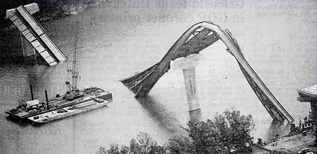
Not all failures are catastrophic. Many failures involve a gradual degradation of properties or excessive deformation or wear until the component is no longer functional. Failures due to wear or general corrosive attack usually are not spectacular failures, but account for tremendous material losses and downtime every year. Of course, early failures of the spectacular catastrophic order capture the most attention-and rightly so. Nevertheless, all failures deserve the attention of the investigator because they reduce production efficiency, waste critical materials, and increase costs. In some instances, they cause considerable damage or personal injury. Finally, failures can result in costly litigations.

Identifying the Cause of Tool and Die Failure

January 6, 2016 by George Vander Voort

Identifying the Cause of Tool and Die Failure

Steels used for tools and dies differ from most other steels in several aspects. First, they are used in the manufacture of other products by a variety of forming processes. Second, tools and dies are generally used at a higher hardness than most other steel products; 58 to 68 Rockwell C is a typical range. Dies for plastic molding or hot working are usually used a at lower hardness, typically from 30 to 55 Rockwell C.

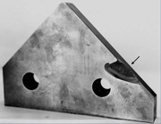
These high hardness values are required to resist anticipated service stresses and to provide wear resistance. However, the steels must also be tough enough to accommodate service stresses and strains without cracking. Premature failure caused by cracking must be avoided, or at least minimized, to maintain minimum manufacturing costs. Unexpected tool and die failure can shut down a manufacturing line and disrupt production scheduling. Tools and dies must also be produced with the proper size and shape after hardening so that excessive finishing work is not required. Heat-treatment distortion must be controlled, and surface chemistries must not be altered. Because of the careful balance that must be maintained in heat treatment, control of the heat-treatment process is one of the most critical steps in producing successful tools and dies. In addition to controlling the heat-treatment process, tool and die design and steel selection are integral factors in achieving tool and die integrity. 

Metallographic Examination of Medical Implants

December 8, 2015 by George Vander Voort

Metallographic Examination of Medical Implants

Medical technology has developed many new devices that can be implanted into humans (in-vivo) to repair, assist or take the place of diseased or defective bones, arteries and even organs. The materials used for these devices have evolved steadily over the past fifty years with titanium and cobalt-based alloys replacing stainless steels. Metallographic examination has become an indispensable tool in the testing, quality control, failure studies and post-mortem analyses of these devices. This paper presents techniques and results for examination of titanium-based acetabular cups and Co-Cr-Mo femoral hip stems and knees. These implants have porous metallic coatings on one side to enhance bone/metal interface adhesion by in-growth of bone into the porous coatings. 

What is a Normal, Uni-Modal Grain Size Distribution?

November 10, 2015 by George Vander Voort

What is a Normal, Uni-Modal Grain Size Distribution?

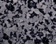
ASTM Test Method E 112 says it covers test methods to determine the average grain size of specimens with a uni-modal distribution of grain areas, diameters or intercept lengths. It says that these distributions are approximately log-normal. But, it does not describe how one can determine if their specimen’s grain size distribution is a uni-modal normal (Gaussian) distribution. ASTM E 1181, Standard Test Methods for Characterizing Duplex Grain Sizes, says it covers test methods to characterize grain size in products with any other distribution (other than a “single log-normal distribution of grain sizes”). But, the only example given in Appendix X2 shows the percentage of the number of intercept measurements in 38 length classes from 0 to 1 to 37 to 38 mm. Thirty eight classes is far too many to properly reveal the grain size distribution. This procedure reveals a log-normal distribution but it is not in terms of ASTM grain size numbers, which makes it less useful. 

Avoid Microindentation Hardness Testing at Low Loads!

October 8, 2015 by George Vander Voort

Avoid Microindentation Hardness Testing at Low Loads!

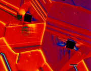
For many years, ASTM E384 has stated that the load range for microindentation hardness testing with both Knoop and Vickers indenters is 1 to 1000 gf. But, it also states that tests that produce a Knoop long diagonal or a Vickers mean diagonal of < 20 gf should be avoided as the precision in measuring such small indents is poor. The standard recommends using loads no lower than 25 gf. This article shows that the Knoop test exhibits better measurement precision at loads of 200 gf and below because the long diagonal is 2.7 times greater in length than the Vickers mean diagonal length for the same specimen tested at identical loads. Knoop, however, does not produce constant hardness values as the load changes, which is a major problem. If one can use a 100X objective with a numerical aperture of 0.95 – while obtaining adequate image contrast – indents as small as 14.7 μm in length could be measured. But, the challenge is to obtain acceptable image contrast at 1000X magnification so that the indent tips can be clearly seen. Realistically, a minimum diagonal length of 20 μm is a better target. 

Image Caption: Aluminum brass, Cu-22% Zn – 2% Al that was solution annealed at 850C (producing a nice coarse grain size – average of ASTM 3.3). The specimen was etched with Beraha’s PbS tint etched and viewed with Nomarski DIC to bring out the deformation around the Vickers indents. The hardness was 57 HV – very soft!  A 500 gf load was used.  And it was taken at 100X.

  • 1
  • 2
  • 3
  • …
  • 9
  • Next Page »
  • Vacuum Heat Treating: Education & Training
    • News & Announcements
  • Vacuum Technology with The Heat Treat Doctor
  • Vacuum Pump Technology: Education & Training
  • Metallography with George Vander Voort
  • Q’s and A’s
  • “What’s Hot!” Newsletter
  • Glossary Metallurgical Terms
voort
Vertical vacuum furnace specifications
horizontal vacuum furnace specifications
Vacuum Furnaces
Vacuum Furnace Zone Rebuilds
Technical Articles and Resources

Specialists in Vacuum Furnace Technology - High Quality Vacuum Furnace Manufacturer

COMPANY

  • VAC AERO Products & Services
  • Company History
  • Certificates & Approvals
  • Employment Opportunities
  • Values & Commitment
  • Corporate Sponsorship
  • Corporate Brochure
  • Terms & Conditions of Use
  • Privacy Policy

FURNACE MANUFACTURING

  • Horizontal Furnace Specs
  • Vertical Furnace Specs
  • Hot Zones
  • Control Systems
  • Custom Vacuum Furnaces
  • Quality Control
  • Service & Support
  • Furnace Request For Quote (RFQ) Form

THERMAL PROCESSING

  • Ontario – Plant 1
  • Ontario – Plant 2
  • Quebec – Thermal Processing Division
  • Specific Heat Treating & Brazing Approvals
  • Metallurgical Services Matrix

COATINGS

  • Quebec Coatings Division
  • HVOF Spray System
  • Specific Coating Approvals
  • Metallurgical Services Matrix

SERVICES & SUPPORT

  • Furnace Rebuilds & Upgrades
  • Hot Zone Rebuilds
  • Process Controls Upgrades
  • Ordering Parts
  • Field Service
  • Training Seminars

© Copyright 2016 VAC AERO - All rights reserved. Site Map Contact Terms and Conditions Privacy