Abstract
For many years, ASTM E384 has stated that the load range for microindentation hardness testing with both Knoop and Vickers indenters is 1 to 1000 gf. But, it also states that tests that produce a Knoop long diagonal or a Vickers mean diagonal of < 20 gf should be avoided as the precision in measuring such small indents is poor. The standard recommends using loads no lower than 25 gf. This article shows that the Knoop test exhibits better measurement precision at loads of 200 gf and below because the long diagonal is 2.7 times greater in length than the Vickers mean diagonal length for the same specimen tested at identical loads. Knoop, however, does not produce constant hardness values as the load changes, which is a major problem. If one can use a 100X objective with a numerical aperture of 0.95 – while obtaining adequate image contrast – indents as small as 14.7 μm in length could be measured. But, the challenge is to obtain acceptable image contrast at 1000X magnification so that the indent tips can be clearly seen. Realistically, a minimum diagonal length of 20 μm is a better target.
Introduction
ASTM E384 has stated for many years that tests with Knoop and Vickers indenters can be performed over the load (force) range from 1 to 1000 gf. But, is it wise to recommend testing at loads below 25 gf, or perhaps even below 50 gf? ASTM E92 is being revised to be reinstated after being withdrawn in 2010. Table 3 in the proposed revision lists objectives, their numerical aperture, and the smallest indent that can be measured with precision, assuming that the image contrast at the highest magnifications listed is adequate to see the indent tips. The recommended minimum diagonal length that can be measured with precision is 14.5 μm using a 100X objective with a 0.95 NA. But, how many microindentation systems offer objectives greater than 40X or 50X? For a 40X objective, with an NA of 0.65, the minimum recommended diagonal length to measure is 21 μm. If the NA of the 40X objective is 0.55, the minimum recommended diagonal length to measure is 25 μm. If the system has a 50X objective, which is less common, and an NA of 0.65, the recommended minimum diagonal length to measure is still 21 μm.
Vickers tests at 25 μm or above usually give essentially the same hardness numbers if you can increase the magnification as the indents become smaller [1, 2]. If the diagonal length is <20 μm, indirect verifications using a certified test block is not recommended. E384 states that the precision in measuring indents <20 μm in length is poor and the data is suspect. Tests that produce indents <20 μm in length should be avoided. Yet, the standard states that the test load range is 1 to 1000 gf. This is inconsistent.
Experimental Data
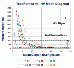
I have calculated HV and HK diagonal values for the range from 100 to 1000, typical for steels from the purest iron available to the surface hardness of a nitrided steel using 1, 10, 15, 20, 25 and 50 gf test forces. Figure 1 shows a plot of HV versus mean diagonal length using these six test forces for the Vickers scale and Figure 2 shows similar data for the Knoop hardness scale. Note that even at a 50 gf load, only a small fraction of the steel hardness range has mean Vickers diagonals ≥ 20 μm.
 |
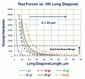 |
| Figure 1: Vickers mean diagonal length versus HV for the 6 test forces. | Figure 2: Knoop long diagonal length versus HK for the 6 test forces. |
Of course, a steel specimen tested with both Knoop and Vickers indenters will not have the exact same Knoop and Vickers hardness number. E140 shows a 20 unit difference in HK vs. HV for steel with 68 HRC hardness and we know that HK will rise for a given specimen as the test force drops below 500 gf with the rise increasing as the test force decreases. HV is higher than HK at 67 and 68 HRC, while HK is greater from 20-66 HRC. At 20 HRC, there is a 13 unit difference between the Knoop hardness (251) and Vickers hardness (238). From 55 to 100 HRB, the HK number is also greater than the HV number. At 55 HRB, the Vickers hardness is 100 while the Knoop hardness is 112. At 100 HRB, the Vickers hardness is 240 while the Knoop hardness is 251. E140 does not state a test force for Vickers because HV is statistically constant from 25 gf to macro loads. E140 (and A370 where the conversions were first published) states that the test force for the Knoop conversions is 500 gf and “greater” (ill defined and incorrect). So the data shown for the Knoop test using the 6 test forces does not take into account that the numbers will increase as the test force decreases for the same specimen. Nevertheless, the comparisons are reasonably valid.
 |
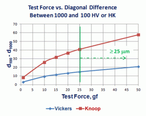 |
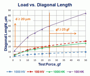
| Figure 3: Test force versus diagonal length for steels with 100-1000 HV or HK. | Figure 4: Difference in diagonal lengths for 100 versus 1000 HV or HK hardness numbers as a function of test force. |
Because the Knoop long diagonal is 2.7 times greater in length than the mean Vickers diagonal for the same test force and same hardness, Knoop diagonals ≥20 μm cover a wider range of steel hardness than does the Vickers test at all test loads shown in Figures 3 and 4. Note that when using a 50 gf load, the entire steel range, from 100 to 1000 HK, yielded long diagonals ≥20 μm. When a 25 gf test load is used, steels from 100 to 889 HK exhibited long diagonal lengths ≥ 20 μm. When a 20 gf load is used, steels from 100 to 711.5 HK exhibited long diagonal lengths ≥20 μm. In contrast, when a 50 gf load is used with the Vickers indenter, steels from only 100 to 231.8 HV will have mean diagonals ≥20 μm while for a 25 gf load, steels from only 100 to 115.9 HV will have mean diagonals ≥20 μm. Going to higher applied forces, with a 100 gf test load, steels from 100 to 463.6 HV will have mean diagonals ≥20 μm and for a 200 gf load, steels from 100 to 927.2 HV will have mean diagonals ≥20 μm in length. This seriously restricts the utilization of the Vickers test at load test loads.
Figure 3 and 4 show plots of the six test forces used versus the mean Vickers diagonal length or the long Knoop diagonal for the 100-1000 hardness number range for steels. Again, it is obvious that the Knoop indenter has greater validity for tests in this hardness range, but there is really no value in recommending use of test forces <25 gf for either test, and especially not for test forces <20 gf. Figure 4 further illustrates the better sensitivity of the Knoop compared to the Vickers test at loads ≥25 gf. For test forces above 25 gf, Knoop has a wider variation in diagonal length, and thus is better able to discriminate minor hardness differences with better precision at 25 or 50 gf test loads than the Vickers test can. Table 1 lists the mean diagonal length or long diagonal length for the Vickers and Knoop tests at 100 and 1000 HV or HK.
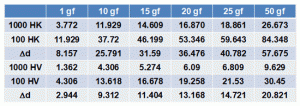 |
| Table 1: d100 – d1000 for Range of Steel Hardness in HV and HK |
Conclusions
These calculations very clearly demonstrate that microindentation hardness tests at loads <25 gf yield indents that are too small to measure with a light optical microscope at 400X or 500X. At 1000X, it is possible to measure somewhat smaller indents than 20 μm. However, at 1000X it is difficult to get strong image contrast in bright field illumination to see where the indent tips are which strongly affects measurement precision. The Knoop indenter produces a long diagonal that is about 2.7 times greater than the mean Vickers diagonal for the same steel hardness and test load. This makes it possible to cover the full range from 100 to 1000 HK with a 50 gf test load as the long diagonal will be ≥20 μm in length. For a 25 gf test load, specimens from 100 to 889 HK will exhibit long diagonals ≥20 μm in length. For the Vickers test, test loads above 200 gf are required to cover the range from 100 to 1000 HV producing mean diagonals ≥20 μm in length.
References
1. George F. Vander Voort and Ryan Fowler, “Low-Load Vickers Microindentation Hardness Testing,” Advanced Materials & Processes, Vol. 170, April 2012, pp. 28-33.
2. George F. Vander Voort, “Obtaining Consistent Microindentation Hardness Data, Part I,” Industrial Heating, Vol. 82, August 2014, pp. 53-58..
George Vander Voort has a background in physical, process and mechanical metallurgy and has been performing metallographic studies for 48 years. He is a long-time member of ASTM Committee E-4 on metallography and has published extensively in metallography and failure analysis. He regularly teaches MEI courses for ASM International and is now doing webinars. He is a consultant for Struers Inc. and will be teaching courses soon for them. He can be reached at 1-847-623-7648, EMAIL: georgevandervoort (at) yahoo.com and through his web site: www.georgevandervoort.com
To View a listing of all George’s articles please click here
Read George Vander Voort’s Biography
