Abstract
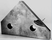 |
| Tool Steel Failure Examples and Metallographic Imagery below. |
Steels used for tools and dies differ from most other steels in several aspects. First, they are used in the manufacture of other products by a variety of forming processes. Second, tools and dies are generally used at a higher hardness than most other steel products; 58 to 68 Rockwell C is a typical range. Dies for plastic molding or hot working are usually used at a lower hardness, typically from 30 to 55 Rockwell C.
These high hardness values are required to resist anticipated service stresses and to provide wear resistance. However, the steels must also be tough enough to accommodate service stresses and strains without cracking. Premature failure caused by cracking must be avoided, or at least minimized, to maintain minimum manufacturing costs. Unexpected tool and die failure can shut down a manufacturing line and disrupt production scheduling.
Tools and dies must also be produced with the proper size and shape after hardening so that excessive finishing work is not required. Heat-treatment distortion must be controlled, and surface chemistries must not be altered. Because of the careful balance that must be maintained in heat treatment, control of the heat-treatment process is one of the most critical steps in producing successful tools and dies. In addition to controlling the heat-treatment process, tool and die design and steel selection are integral factors in achieving tool and die integrity.
Tool and die failures caused by breakage, which are generally catastrophic, are the most spectacular and draw the most attention from the failure analyst. Such failures are usually the easiest to diagnose, but the analyst should not halt the investigation when one obvious problem is identified. Several factors can contribute to a failure in varying degrees. The goal of any failure analysis should be to provide a total picture of all problems present so that complete corrective action can be taken on future parts.
Aside from cracking, a variety of problems can be encountered that cause limited tool or die life. These include, but are not limited to, excessive wear, galling, pickup, erosion, pitting, cosmetic problems, corrosion problems, and distortion during heat treatment, machining, or service.
Gathering Evidence
Knowing the manufacturing and service history of a failed part can aid in the analysis of tool and die failures. In many instances, however, such information is sketchy, and the analyst must rely on experience and engineering judgment. A basic approach can be followed for most tool and die failures to maximize the likelihood of identifying reasons for the failure. At times, however, no reason for failure can be discovered. In such cases, the failures are usually attributed to unknown service conditions.
Before beginning the investigation, a complete history of the manufacture and service life should be compiled if possible. Next, the part should be carefully examined, measured, and photographed to document the extent and location of the damage. Relevant design features, as well as some machining problems, are generally apparent after this study. The origin of the failure, when caused by fracture, will also usually be determined.
Only after a careful visual examination has been completed should any destructive work be considered. In certain cases, various non-destructive examination techniques – ultrasonic, X-ray, or magnetic particle inspection – should be implemented before cutting to obtain a more complete picture of the damage, either internal or external.
When this work is completed, several other phases of the study can begin. First, the composition of the component should be verified by a reliable method. Tool and die failures occasionally result from accidental use of the wrong grade of steel.
While this work is under way, the analyst can continue macroscopic examination of the fracture features by opening tight cracks, if they are present. Because quench cracking is a common cause of failures, the fracture surfaces should always be checked for temper color. Scale on a crack wall would indicate that it was exposed to temperatures higher than those used in tempering.
Visual inspection of the damage done to a tool and die is usually adequate to classify the type of failure. High-magnification fractographic examination is required in only a small percentage of cases. A simple stereomicroscope examination generally suffices. If this indicates that something may be present at the initiation site, then SEM examination and EDS or WDS analysis would be required.
Microstructural examination at and away from the damaged area and at the origin is imperative. This generally requires good edge-retention preparation, which is relatively easy for tool steels. A large percentage of tool and die failures are caused by heat-treatment problems; the value of proper metallographic procedures cannot be stressed enough.
Other techniques are also important. Hardness testing is used to confirm the quality of the heat treatment and often reveals problems. Macrostructural examination, either by cold or hot etching, is useful for detecting gross problems. Prior-austenite grain size is frequently evaluated by the Shepherd fracture grain size technique, a simple but accurate approach. X-ray diffraction can be used to determine the amount of retained austenite present.
In some cases, performing simulations or conducting experimental heat treatments, for example, to determine if a part was tempered, are necessary. Chemical analysis of millings or turnings from the surface will define variations in surface carbon content. Electron metallographic devices using either wavelength- or energy-dispersive X-ray analysis can be used to identify inclusion or segregates. Comparing the characteristics of good parts to those of failed parts is also helpful in some studies.
When this data is compiled and analyzed, the analyst is ready to prepare a report that details the cause of failure with the supporting facts. In many cases, making recommendations regarding corrective action for future or existing parts is necessary.
Factors to Consider
A number of factors can be responsible for tool and die failures. They include:
1. Mechanical design. The design must be compatible with the steel grade selected, the procedures required to manufacture the tool or die, and the use of the tool or die.
Any examination of tool or die failures must begin with a careful re-examination of the design to determine if shortcomings are present and if improvements can be made. Tools and dies that perform satisfactorily over the desired service life may not work as well if a new manufacturing process is adopted, the grade is changed, or service conditions are altered. Consequently, obtaining complete details on the history of the component is imperative.
The importance of good design cannot be overemphasized. Poor design can cause or promote heat-treatment failures before any service life is obtained, or it may reduce service life dramatically.
In designing a tool or die, a host of factors must be considered. In practice, separating the design stage from grade selection is difficult because the two steps are interdependent. The choice of a certain grade of steel, such as one that must be brine- or water-quenched, will have a substantial bearing on all aspects of design and manufacture. In general, any steel grade that requires liquid quenching demands very conservative, careful design.
Air-hardening grades tolerate some design and manufacturing considerations that could never be endured by a liquid quenching grade. The design must also be compatible with the equipment available – heat-treatment furnaces and surface-finishing devices, for example.
Designing tools and dies is more difficult than designing components made from structural steels because of the difficulty in predicting service stresses. Despite advances made in design procedures, much design work is still empirically based. Experience is primarily based on past failures; therefore, the findings of the failure analyst must be incorporated into future work. Despite the shortcomings of the empirical approach, a vast body of common-sense engineering knowledge is available for guidance.
2. Grade selection. The grade of steel selected must be compatible with the design chosen, the manufacturing processes used to produce the tool or die, and the intended service conditions and desired life.
Selection of the optimum grade for a given application is generally a compromise between toughness and wear resistance, although other factors may be more important in certain situations. Because most tools and dies operate under highly stressed conditions, toughness must be adequate to prevent brittle fracture. It is usually better for a tool or die to wear out than to break in service prematurely.
Thus, in a new application, selecting a grade that is sure to have adequate toughness is best. As experience is gained, the best grade choice can be made by balancing the required toughness and wear resistance. If experience shows the tool or die is free from breakage but sustains excessive wear, for example, a different grade can be selected to provide better wear resistance but somewhat less toughness.
3. Steel quality. The material must be macrostructurally sound, free of harmful inclusions to the degree required for the application, and free of harmful surface defects.
Despite the care taken in the manufacture and inspection of tool steels, faulty materials occasionally cause tool and die failures. However, such problems are rare. The most common of these defects are voids from secondary pipe, hydrogen flakes, surface cracks, porosity or microvoids, cooling cracks, segregation, and poor carbide distributions. Improper control of annealing may also produce non-uniform carbide distribution or carbide networks that may influence heat-treatment uniformity, lower ductility, or impair machinability.
4. Machining processes. The machining processes used to produce the tool or die must not alter the surface microstructure or surface finish and must not produce excessive residual stresses that will promote heat-treatment problems or service failures.
Machining problems are a common cause of tool and die failures. It is generally best to avoid machining directly to the finish size unless pre-hardened die steels are used. Obtaining perfect control of surface chemistry and size during heat treatment is difficult. Thus, some final grinding is usually needed after heat treatment. The presence of decarburization is generally quite detrimental. Also, because stresses are high in heat treatment and in service, rough machining marks must be avoided. Identification stamp marks are another common source of failures in heat treatment and in service; they should be avoided.
5. Heat-treatment operation. Heat treatment of tools and dies must produce the desired microstructure, hardness, toughness, and hardness at the surface and in the interior.
Improper heat-treatment procedures are the single largest source of failures during heat treatment, in subsequent processing steps, or in service. Each tool steel grade has a recommended austenitizing temperature range, which is generally rather narrow; a recommended quench medium; and recommended tempering temperatures and times for optimum properties. Some grades are more forgiving than others.
6. Grinding and finishing operations. Grinding and finishing operations must not impair the surface integrity of the component.
7. Tool and die setup. Alignment of tools and dies must be precise to prevent irregular, excessive stresses that will accelerate wear or cause cracking.
8. Tool and die operation. Overloading must be avoided during operation to ensure that the desired component life is achieved.
Tools and dies, although made from the correct grade, well designed, and properly machined and heat treated, can fail after limited service because of improper operation or mechanical problems. In such cases, the failure analyst may spend considerable effort evaluating the design, grade selection, machining, and heat treatment without uncovering any abnormalities. In many cases, the analyst has little information concerning the use of the tool and can only conclude that service problems were responsible for the failure. In some cases, evidence of the mechanical or service problem may be present.
Mechanical factors that may cause premature failures include overloading, overstressing, and alignment or clearance problems. Excessive temperature may be a factor in hot-working die failures, perhaps because of inadequate cooling between operations. Failures have also occurred during assembly-for example, during shrink fitting of one part onto another. Stamp marks, in addition to causing heat-treatment failures, can cause service failures due to stress concentration.
Alignment problems are a common cause of failure of tools used in shearing operations. While most tools and dies fail in a brittle manner, fatigue failures are sometimes encountered. In most cases, the fatigue failure is located at a change in section size, at a sharp corner, or at stamp marks.
Interdependence
This classification of factors can be helpful in categorizing problems, but it will not necessarily deduce the cause of a particular failure. A failure caused by one problem may have been precipitated by other problems earlier in the processing sequence.
For example, many cracking problems attributed to abusive grinding practices are caused by failure to temper the part or by over-austenitization. Both of these problems will make a tool steel almost impossible to grind without producing surface burning and cracking, regardless of the care taken during grinding.
Thus, these factors are interdependent, much like the links of a chain. If one step is poorly executed, the tool or die will have a limited service life regardless of how carefully all of the other steps are conducted. This sensitivity to processing stems from the use of tools and dies at very high hardness levels, at which minor deficiencies in processing exert major influences on performance.
Tool Steel Failure Examples
 |
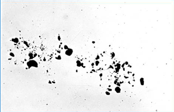 |
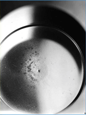
| Pits on Polished Face of AISI A2 Tool Steel Mold. | Holes in Region with Carbide Segregation, 100x |
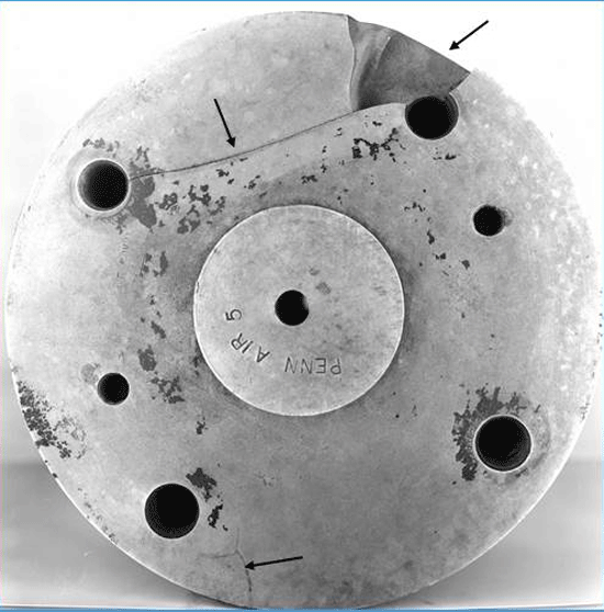 |
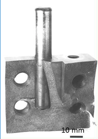
| A2 Stamping Die – Broke Due to Unintentional Carburization – 8-inch Diameter Die |
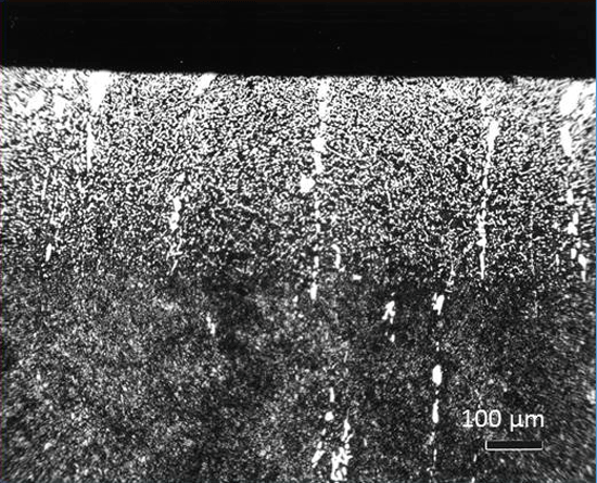 |
| A2 Stamping Die – Broke Due to Unintentional Carburization – 3% Nital |
 |
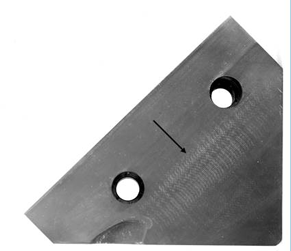 |
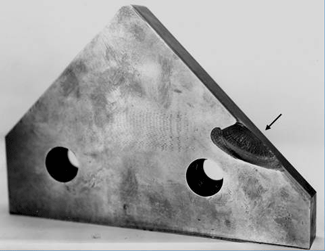
| S7 Angle Shear Blade – This S7 angle shear blade failed prematurely due to grinding abuse caused by an unstable microstructure at the surface. | |
 |
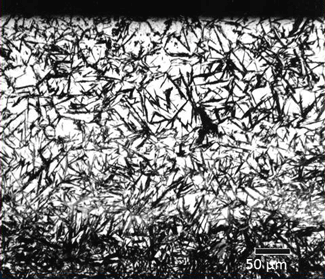
| Failed Over-Austenitized A2 Rotary Knife. |
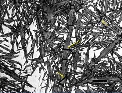 |
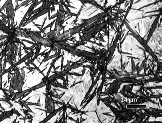
| Retained austenite and very coarse plate martensite with micro-cracks (arrows), 3% nital, 700x. |
 |
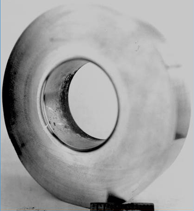 |
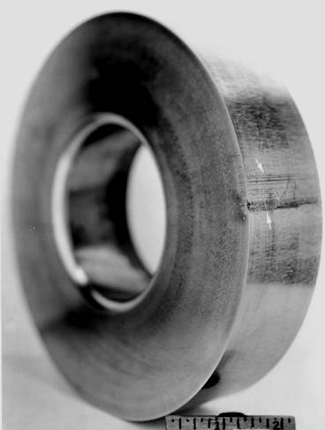
| D2 Draw Die Insert – Incipient Melting – OD Damage | D2 Draw Die Insert – Incipient Melting – ID Damage |
 |
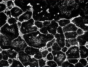 |
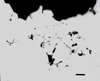
| D2 Draw Die Insert – Incipient Melting – OD Damage | Interior, Marbles Reagent |
| The ID and OD surface damage was due to incipient melting of the alloy during heat treatment. |
|
 |
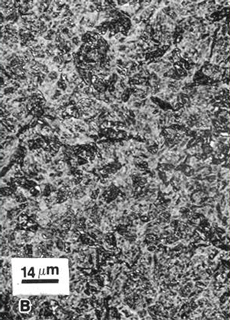 |
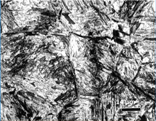
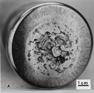
| Under-Austenitization – L6 Punch | This AISI L6 punch was used to grind coffee beans but failed after a short service life because it was under-austenitized and was below the specified hardness. |
 |
| Torsion Twist Failure in AISI S7 Super-duty Dragster Axle Axle was never heat treated! |
George Vander Voort has a background in physical, process and mechanical metallurgy and has been performing metallographic studies for 48 years. He is a long-time member of ASTM Committee E-4 on metallography and has published extensively in metallography and failure analysis. He regularly teaches MEI courses for ASM International and is now doing webinars. He is a consultant for Struers Inc. and will be teaching courses soon for them. He can be reached at 1-847-623-7648, EMAIL: georgevandervoort@yahoo.com and through his web site: www.georgevandervoort.com
To View a listing of all George’s articles please click here
Read George Vander Voort’s Biography

