By Carmine Filice, Daniel H. Herring, Paul Vanderpol
The main components of a landing-gear structure are wheels and brakes, axles, bogie beams (a.k.a. truck beams), shock absorbers (a.k.a. shock struts), and drag and side braces. Primary design considerations on landing gear include maximum sink speed, spin up, spring back, lateral drift (on landing), towing, jacking, turning, braked roll, taxi, rebound, pivoting (main landing gear only), crashworthiness and fatigue.
![Fig. 1. Landing incident at LAX International Airport –jammed nose wheel Airbus A320-232[1]](https://vacaero.com/wp-content/uploads/2011/12/ih1111-vst-fig1-lg-1.gif)
Secondary loads include retraction/extension, aerodynamic loads, lock/unlock loads and emergency extension. In addition, nose landing-gear specific forces include dynamic breaking, nose-gear yaw and steering. Alloys used in these applications must have high strengths, normally between 260-300 ksi (1,792-2,068 MPa).
Vacuum Oil Quenching
To achieve their design and performance goals, landing-gear specifications and cycles have been developed to extract the optimum heat-treat response (and mechanical properties) from these alloys. Vacuum heat treatment followed by oil quenching and double tempering produces a microstructure with high strength and excellent toughness, ideal for applications involving heavy loading and fatigue. During hardening, internal stresses created from the thermal shock of direct oil quenching almost always cause some degree of distortion in these components. A final machining allowance is often left on critical dimensional features to compensate for distortion. Due to the difficulty of machining these alloys in the hardened condition, however, machining allowances must be minimized. In the current environment of cost and lead-time pressures, reducing distortion during thermal processing has become a primary objective for heat treaters of landing-gear components.
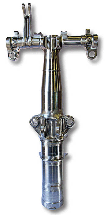
Vacuum oil quenching offers the economic and environmental benefits for processing these critical-performance components. This is especially true for the bogie beam (Fig. 2). Since vacuum furnaces are inherently leak tight, control of surface chemistry is assured, and problems with decarburization and high-temperature oxidation are avoided. Vacuum processing also allows producers of aircraft landing gear to finish machine critical surfaces on these components prior to heat treating. This, in turn, reduces final machining costs when the part is in the hardened condition. Further, quench-related distortion is minimized through load transfer to the quench tank via high-speed elevator.
Heat treaters equipped with vertical vacuum oil-quench capability are well suited for processing landing-gear components. Since section thicknesses are large, fast to medium-fast oil quenchants are typical so as to achieve the through-hardened microstructure requirements. Large variations in hardness (surface to core) cannot be permitted.
Racking and fixture design are also critical to ensure the parts heat uniformly, do not experience thermal distortion (which can be considerable) and enter the oil in a vertical orientation for uniform heat transfer along the length of the parts.
How it Works
Style 40 Furnace
The Style 40 furnace (Fig. 3), commissioned in 1989 and still in operation today, can handle workloads up to 1,600 kg (3,500 pounds) and 1.8 m (72 inch diameter) x 2.9 m (114 inch) tall. Landing-gear components are loaded vertically onto a support fixture.
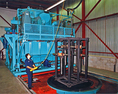
The furnace heating chamber is mounted on a movable gantry. During loading, the gantry moves aside and the load is placed onto the quench elevator. Prior to this, the quench oil is transferred to a reservoir tank so as to avoid contact with the load prior to entry into the vacuum chamber. The elevator lowers the load into the empty quench tank, and the heating chamber moves into position over the quench tank, then lowers and seals to the quench-tank flange.
A vacuum seal door and hearth doors within the heating chamber open, and the elevator raises the load into the heating chamber. As the elevator withdraws into the quench tank, the hearth doors close to support the load and the seal door closes to isolate the heating chamber. After the loading sequence is complete, the quench oil is pumped back into the quench tank from the reservoir tank.
After pumpdown, ramping and stabilizing at the hardening temperature, the chamber is backfilled with nitrogen gas to equalize the pressure between the chamber and the oil quench tank. The furnace doors then open, and the elevator raises to support the load and then descends quickly (within 10 seconds) into the 40,000-liter (10,500-gallon) quench tank to complete the process.
Style 80 Furnace
The Style 80 furnace (Fig. 4), commissioned in 2009, is capable of running workloads up to 1,600 kg (3,500 pounds) and 1.8 m (72 inch) diameter by 1.9 m (76 inch) high. Parts are loaded vertically onto a support fixture. The furnace bell is raised into the up position, exposing the hearth table. The seal door separating the quench tank from the hot zone is closed. After the load is placed on the hearth table, the loader is retracted out of the furnace and the bell is lowered.
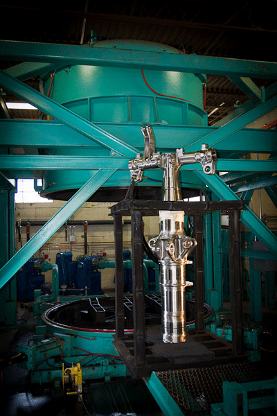
The furnace is pumped down and processing commences. During processing, the furnace chamber is evacuated to a pressure of approximately 10-2 mbar (7.5 x 10⁻³ torr). The oil quench tank is also evacuated to a pressure of approximately 400 mbar (300 torr). When chamber evacuation reaches a preset pressure, heating of the load starts until the recommended austenitizing temperature (Table 1) is achieved.
Heating ramp rates are selected to minimize thermal gradients within the load without creating excessive cycle times. Control of the ramp rate during heating is an important factor in relieving stresses that may have been created during machining of the components being heat treated. During heating, the load is also held at an intermediate temperature around 620°C (1150°F) for a short period of time to further improve temperature uniformity. Maintaining temperature uniformity throughout the cycle is essential to prevent the buildup of thermal stresses and to ensure that all sections of the load undergo the microstructural transformations needed to achieve the desired mechanical properties.
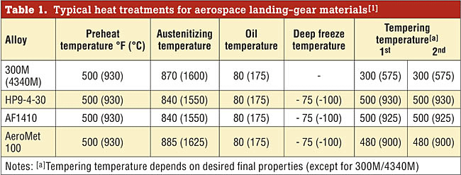
After the load is soaked for a sufficient period of time at the austenitizing temperature, the oil quenching process can begin. The first step in this process is the backfilling of the furnace chamber (with nitrogen gas) to 400 mbar (300 torr) or just below atmospheric pressure to equalize to the pressure in the oil quench tank between the furnace and the oil quench.
Next, the vacuum seal door is opened and the quench elevator is raised to a point where it again supports the weight of the load. The load bars are then retracted, and the elevator and load rapidly descend (within 10 seconds) into the quench tank. After the load is lowered into the quench tank, power to the heating elements is shut off and the seal door is closed. The quench blower is then activated to cool the heating chamber to ambient temperature. The quench tank contains 35,000 liters (9,300 gallons) of quench oil. Electric heaters and coolers regulate oil temperature. Careful monitoring of quench-oil conditions is an important factor in part distortion control.
At the end of cycle, the furnace is backfilled with nitrogen to atmospheric pressure and the bell is raised to the up position. The seal door opens up, and the elevator raises the load out of the oil (at slow speed) to the up position. The load bars extend, and the elevator lowers the hearth table and load onto the load bars. The elevator then lowers to standby position just below the seal door. The seal door closes, and the loader moves in to unload the parts from hearth table.
Style 100 Furnace
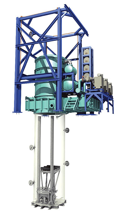
VAC AERO International’s furnace manufacturing division is presently building a larger oil quench vacuum furnace (Fig. 5) capable of running 1,800 kg (4,000 pounds) workload dimensions of 1.8 m (72 inch) diameter by 3.5 m (138 inch). This unit is expected to be qualified and production-ready by the third quarter of 2012.
Product Analysis & Testing
By their very nature, landing-gear components are complex machined parts with numerous section changes and transitions. As such, landing-gear manufacturers do extensive design and structural analysis to ensure proper product performance. Structural analysis determines such factors as limit loads (so no detrimental permanent deformation occurs) and ultimate loads (so no rupture, collapse or other failure modes occur) where ultimate loads are typically 1.5 times limit loads.
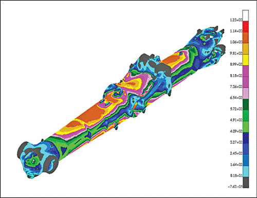
Component finite element analysis (FEA) methods (Fig. 6) using solid models support fatigue analysis and identify stress concentrations (so-called “hot spots”). These techniques are now also employed for ultimate performance analysis (e.g., linear elastic FEA with traditional margin-of-safety calculations, non-linear elasto-plastic analysis (so-called “Riks” collapse analysis) and advanced analysis techniques (e.g., pin/socket joint contact and non-linear “collapse” analysis) as well as
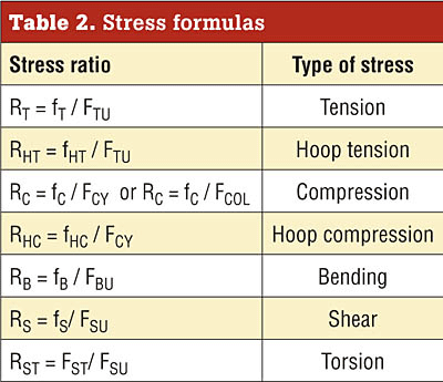
Margin-of-safety calculations are used with load or stress calculations. In most situations, a component or section of a component experiences more than one type of load or stress simultaneously, so individual load (or stress) ratios and a utilization factor is calculated (Eq. 1).
R = Applied Load/Allowable Load or R = Applied Stress/Allowable Stress (1)
Where R = Load (or Stress) ratio
A subscript is normally used to indicate the type of load ratio (Table 2). A lower-case f is used for applied stress, and an upper-case F is used for allowable stress.
Structural analysis is performed on such components as sockets, lugs, pins, columns and bearings. These sections are under combined loads including:
- Axial loads in tension = fT or FTU
- Column axial loads in compression = fC or FCOL
- Local crippling loads in compression = FCC
- Shear loads = fS or FSU
- Bending modulus of rupture = fB or FBU
- Torsional modulus of rupture = FST
- Hoop stress = FTU (pcrit)
A utilization factor (i.e. “factor of utilization in combined loading”) is then calculated, as is the margin of safety (Eq. 2).
M.S. = 1/U – 1.0 (2)
where U = utilization factor; M.S. = margin of safety
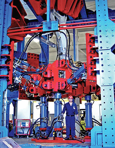
Testing (Fig. 7) confirms the results of FEA and combined loading calculations.
Conclusions
Experience in the heat treatment of landing-gear components and using the right supplier partner is critical, as is having the right type of equipment, controls and cycle repeatability to ensure that the rigid standards of the aircraft industry are met or exceeded.
Paul Vanderpol, Goodrich; Oakville, Ontario, CANADA
Carmine Filice, VAC AERO International Inc.; Oakville, Ontario, CANADA
Daniel H. Herring / Tel: (630) 834-3017) /E-mail: dherring (at) heat-treat-doctor.com
Dan Herring is president of THE HERRING GROUP Inc., which specializes in consulting services (heat treatment and metallurgy) and technical services (industrial education/training and process/equipment assistance. He is also a research associate professor at the Illinois Institute of Technology/Thermal Processing Technology Center.
Reference
- www.AirlineSafety.com
- Mackenzie, Scott, “Heat Treatment of Landing Gear,” Heat Treating Progress, Volume 8, Issue 3, May/June 2008.
- Pritchard, Jeff, “Advanced Techniques for Distortion Control During Oil Quenching,” 17th ASM Heat Treating Society Conference Proceedings, ASM International.
