In simplest terms, backstreaming is the movement of pumping fluid back into the vacuum furnace chamber, that is, oil vapor molecules attempt to reverse course and move up and back toward the vacuum vessel, opposite to the direction of the desired gas flow. Backstreaming is not limited to the pumps themselves, but encompass the entire pumping system (e.g. plumbing, valves, baffles, and traps). The oil type and characteristics play a role as well. In all cases, the result of backstreaming, namely the contamination of the work chamber or workload, is totally unacceptable and often catastrophic.
Backstreaming is often due to:
- Incorrect start-up or shutdown procedures – the far most common operator mistake as far as the writer is concerned;
- Exceeding maximum pump throughput capacity for long periods of time;
- Exceeding the critical discharge pressure in the foreline.
Users of vacuum furnaces should be sure that the vacuum system is equipped with all the appropriate interlocks to prohibit vacuum valve cycling above specified pressures that can cause these effects to occur, which will help protect your system, especially whenever it is left unattended.
Mechanical Pumps
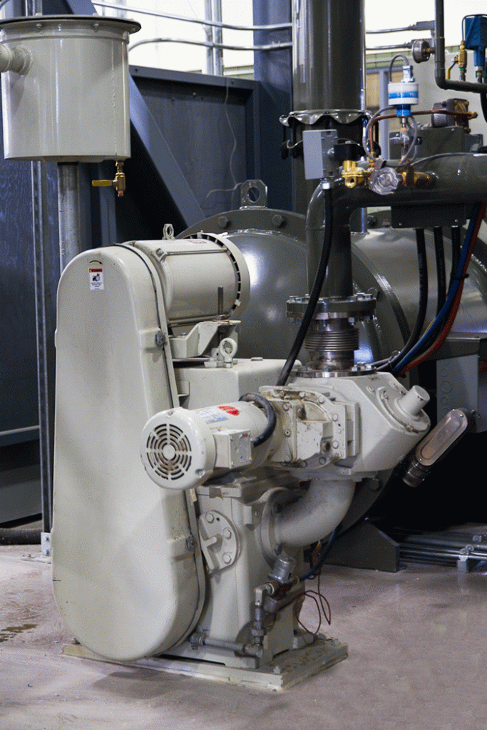
Mechanical vacuum pumps (so-called wet pumps) are commonly used in the heat treating industry (Fig. 1) to obtain chamber pressures at or below 1 x 10⁻¹ torr (100 microns). These pumps contain oil for sealing, lubrication, and cooling of internal moving parts. The presence of oil vapors at the inlet of the pump provides the possibility of backstreaming and contamination of the vacuum system. If the oil reaches its vaporization point, it will turn into a gas and migrate back into the system being evacuated. Normally automatic valves and gauges are provided to start and stop pumping and will prevent a number of backstreaming issues as well as keep the oil cool, reducing its vapor pressure.
Crossover From Rough to High Vacuum
The degree of backstreaming from the mechanical pump depends on the nature of the lubricating fluid, its temperature and the friction conditions at the sliding surfaces inside the pump. Most manufacturers have dimensional tolerances between rotating and stationary parts specifically designed so as to obtain a low degree of back-leakage and assure achieving low ultimate (pump-down) pressures. However, when pumps are used only for initial evacuation and backing of high vacuum pumps the lowest ultimate pressures are not required.
On vacuum furnace systems equipped with diffusion pumps, the question is often asked, when should the high vacuum valve be opened? The switchover (i.e. crossover) point from rough vacuum to high vacuum pump ideally should be done when the gas flow into the high vacuum system is below the maximum throughput of the next pump. Practically speaking, this crossover is normally between 0.067 – 0.20 mbar (50 – 150 microns). Below this range, mechanical pumps are rapidly losing efficiency and the possibility of backstreaming from the pump increases dramatically.

As the pressure falls into the range of 1 x 10⁻² to 1 x 10⁻⁴ torr, a slight decrease in the backstreaming rate is noticeable. Then from about 1 x 10⁻⁴ torr to the lowest achievable vacuum level of the system, the backstreaming rate appears to be independent of the pressure, suggesting that the oil-gas collisions are not significant in these regions.
Although the throughput of the high vacuum pump is nearly constant in the region of 10-1 to 10-2 torr (1 – 100 microns) inlet pressure, the initial surge of gas into the pump, when the high vacuum valve is opened, will overload the high vacuum valve temporarily. The sudden increase of backstreaming at inlet pressures above 10-3 torr points out that a vapor jet pump should not be operated in this range form more than a very brief time. The general recommendation is to keep the period of inlet pressure exceeding 10-2 torr (1 micron), or 10-3 torr (0.5 microns) for larger pumps, in the order of a few seconds. Traps are often used to minimize oil backstreaming from the pumping system (see below).
It is common practice in vacuum system operation to open the high vacuum valve after the chamber is pumped to above 10-1 torr, exposing the diffusion pump to this pressure. Extended operation at these pressures will result in unacceptably high amounts of oil backstreaming into the vacuum system.
Diffusion Pumps
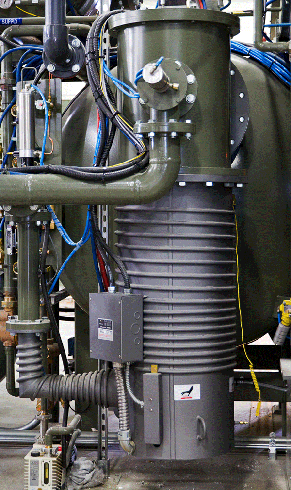
With respect to diffusion pumps (Fig. 2), the most common sources for backstreaming include:
- Collisions between gas and vapor molecules, particularly at high gas loads (e.g. in the 10-3 to 10-4 torr pressure region);
- Boiling of the returning condensate just before the entry into the boiler (between the jet assembly and the pump wall), which results in sending fluid droplets upward through the vapor jet;
- The flow of vapor from the rim of the upper nozzle;
- Poorly sealed penetrations at the top nozzle cap;
- Inter-collision of vapor molecules in the upper layer of the vapor stream from the top nozzle;
- Evaporation of condensed fluid from the pump wall.
Excluding normal backstreaming, the fluid may be lost out of the pump by prolonged exposure above or near maximum throughput, accidental high pressure and high-velocity air flow through the pump (in either direction) or high vapor pressure fluids (due to incorrect temperature distribution). Most if not all of these can be corrected by good design and proper maintenance practices. Primary backstreaming (all of the items listed above which can be prevented by a room temperature baffle) can also be effectively controlled by use of cold traps.
Diffusion Pump Fluid Level
The oil level in a well-designed diffusion pump need not be precisely controlled – generally 30% above or below the manufacturer’s recommended “normal” level should be acceptable (that is, tolerated by the vacuum system without seeing any noticeable effects). When the level is low, the boiling process may pass from nucleated boiling to partial film boiling (in other words, overheating of the boiler surface may occur and the fractionating (breakdown) of the oil can produce a carbonaceous residue. Common indications of this condition are paint discoloration on the exterior of the boiler, or in some extreme cases, distortion of the boiler itself. This problem may result in the exposure of the center of the boiler plate above the liquid level further exacerbating the problem and causing additional overheating. Poor contact between the heater and the boiler plate may also cause overheating and premature failure of the heating elements.
Traps
Several types of traps are commonly used to prevent backstreaming, which can be categorized as:
- Condensation (e.g. cold) traps
- Absorbent (so-called “room temperature”) traps;
- Adsorbent traps.

All three types are designed with a single principle in mind, namely to stop or significantly reduce the volume of vapor emanating from the pumping system. Ideally, a trap should capture any and all oil molecules that enter it, but the reality is, depending on the type and maintenance stature, each has varying degrees of success. The more critical the process application and/or the more sophisticated the pumping demands on the vacuum system best determines the need for the installation of some type of trap.
Each type uses a different trapping mechanism but is in one of two general configurations, bucket designs (the most common) and U-tube designs, each strategically located in vacuum piping between the chamber and the pump. Let’s briefly review each type:
- Condensation traps (i.e. cold traps or liquid nitrogen traps) provide a cold surface to allow condensation of oil vapor to a liquid (or in some cases, solid) form. Coolants can be as simple as water/ice or a dry ice/water slurry to liquid nitrogen (LN2), which is the most common. WARNING, if the trap runs out of coolant and warms up, it can release all of the trapped oil that has collected in its chamber with devastating consequences.
- Absorbent traps use a medium of some sort to trap then absorb oil vapor molecules and retain them. Common media include molecular sieves (the most common) in which there are a number of material choices and alumina balls. WARNING, the sieve will also trap water molecules and does so preferentially allowing oil to still enter the chamber. As such, most traps have an internal heater to regenerate the molecular sieve and drive out water vapor. It is important to flush the trap with nitrogen from upstream to prevent oil fumes vaporized from heating to enter the vacuum chamber. Replacing the molecular sieve on a frequent basis is even a better solution. These types of absorbent traps can also liberate solid particles in the form of a “dust” that can also enter the chamber.
- Adsorbent traps work by attracting and holding oil molecules on a large total surface area material such as finned copper, which can be removed and cleaned once contaminated. An added advantage is that they do not need to be cooled or heated.
Finally, it is important to recognize that any trap will cause a loss of pumping speed so it may be necessary to re-engineer the system if it was not originally designed for the type of trap in use. A trade-off between pumping speed and pump inlet pressure range is given in most cases by the pump speed curve when the pump is used with baffles or traps (the constant speed region is extended to higher pump inlet pressures at the cost of some reduction in net speed.) These pressure and speed tradeoffs can be made only if the maximum throughput of the pumping system is not exceeded. Backstreaming traps can be highly effective if a proper balance if found between the application and the maintenance demands of the trap.
Summing Up
In a well-designed vacuum system, the pump fluid should contribute almost nothing to the total pressure in the vacuum vessel. If contaminants exist they are present due to backstreaming, pump fluid that migrates along the walls of the system (often assisted by vibration) or diffusion pump oil that has fractionated in the diffusion pump boiler. Traps are effective in mitigating these problems as is the substitution of other types of pumps (e.g. getter-ion pumps or cryogenic pumps) but cost and other disadvantages do not make them popular choices for heat treating systems.
References
- Methods of Experimental Physics, Vol. 14, G. L. Weissler and Robert Warner Carlson (Eds.), 1979, Academic Press.
- Brunner Jr., William F. and Thomas H. Balzer, Practical Vacuum Techniques, Robert E. Krieger Publishing Company, 1974.
- Herring, Daniel H., Vacuum Heat Treatment, BNP Custom Media II, 2012.
- Handbook of Vacuum Science and Technology, Dorothy M. Hoffman, Bawa Singh and John H. Thomas III (Eds.), Academic Press, `998.
- Hablanian, Marsbed, H., High-Vacuum Technology: A Practical Guide, Marcel Dekker, Inc., 1990.
- Dushman, Saul, Scientific Foundation of Vacuum Technique, 2nd Edition, J. M. Lafferty (Ed.), John Wiley & Sons, 1966.
- Tsutsumi, Y. and S. Ueda, M. Ikegawa, and J. Kobayashi, Prevention of oil vapor backstreaming in vacuum systems by gas purge method, Journal of Vacuum Science and Technology A, Volume 8, Issue 3 (1990).
- Danielson, Phil, Backstreaming Traps for Oil-Sealed Pumps, A Journal of Practical and Useful Technology.
