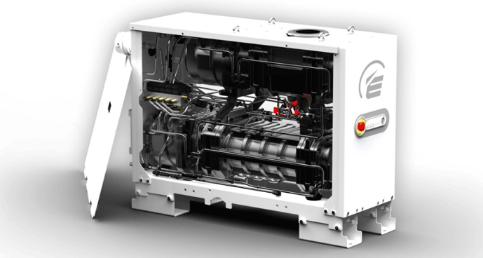
Dry pumps are becoming increasingly popular as an alternative to oil sealed rotary vane pumps for many medium and high vacuum applications (e.g., in low-pressure vacuum carburizing where fine granular soot is carried from the process into the pump). Designers and users of vacuum furnaces must have a good understanding of how claw and screw pumps operate. This includes the principles of operation, pump design, sealing, operating characteristics, features, purging, and ancillary devices.
A dry screw pump (Fig. 1) is used alone when high vacuum is not required and a slower drawdown is allowable, or with a Roots blower (aka booster) when higher performance is required. For the highest system performance, both a Roots booster pump and a secondary high-vacuum (e.g., diffusion) pump are utilized with the primary pump, which provides the fastest pumping speed and highest ultimate vacuum. When used in series with either a booster pump, or with both a booster and secondary high-vacuum pump, the primary pump is referred to as a “backing” pump.

Principle of Operation
Of the various vacuum pump technologies, screw pumps are considered dry, positive displacement pumps. Dry, because the gas being transferred is not exposed to oil or water used in the pump, whereas wet pumps use oil or water as a lubricant and help provide a seal. Positive displacement refers to the fact that the pump works by mechanically trapping a volume of gas and moving it through the pump, creating a low pressure on the inlet side.
Screw Pump Design
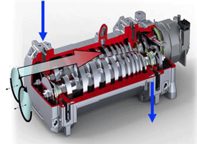
A dry screw pump (Fig. 2) utilizes two intermeshing helical rotors mounted in parallel, which rotate in opposite directions at high rotational speeds without touching. The rotation is synchronized through the use of a precision gear drive arrangement, with each screw rotor mounted to a separate shaft. The rotors can be constant pitch (number of threads per unit length), or utilize a decreasing, tapered pitch, which provides compression of the gas while transporting it. The process gas flow moves axially along the screws in a straight path from inlet to outlet. As the screws counter rotate, voids of increasing volume in front of the rotor chamber are created, drawing in the process gas. Compartments of the gas are trapped within the spaces between the rotors and the housing, and are transported to the discharge, with each turn of the thread serving as a pump stage. The screw threads are tapered at the discharge end, reducing the trapped volume and compressing the gas. The compression at the discharge port discharges the trapped gas against atmospheric pressure.

In rotors with a variable pitch design, the threads on each rotor serve as separate stages in series as the pitch decreases. The gas at the inlet is first transported by the lower pitch section of the rotor (which has fewer threads per unit length) and then by the higher pitch section (having more threads per unit length). In the higher pitch portion, internal compression of the trapped gas occurs. A variable pitch rotor achieves gas compression using less power than a constant pitch rotor. Because less energy is required, the motor size of the variable pitch rotor is smaller and the discharge gas temperature is lower. In a continuous variable pitch rotor design, the trapped gas is continually compressed from inlet to discharge with the highest energy efficiency and the lowest discharge gas temperature. The rotors utilize one of several types of threads, referred to as the Lysholm, the square thread, and the Quimby design. Each has its own pumping characteristics and compression ratios.
The operation of the screw pump can be separated into 5 phases (Fig. 3), as follows:
- Phase 1: Gas enters inlet cavity. Screw rotors rotate at high speed and create inlet cavities between the rotors and the stator.
- Phase 2: Gas is sealed from inlet. As the screws continue to rotate, the cavity becomes a sealed cavity separated from the pump inlet.
- Phase 3: Gas is displaced along the pump axis. Relative motion of the screws causes the trapped gas pocket to be transferred from the inlet toward the outlet.
- Phase 4: Back leakage. As the gas is transferred, some back leakage (back flow) occurs, whereby a small amount of gas leaks between the surfaces the rotors and the stator against the direction of gas transfer.
- Phase 5: Gas exits the pump. The trapped gas is transferred to the pump outlet at atmospheric pressure, creating the pumping action.

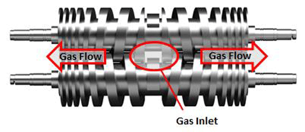
Screw pumps can be single ended, where the gas enters at one end and exits at the other, or double-ended (Fig. 4), where the gas enters in the middle and exits both ends of the pump. Dry screw pumps can provide a typical ultimate vacuum of 3.7 x 10⁻⁴ Torr pumping speeds of 900 m3/h (560 cfm) while exhausting into atmospheric pressure.

Pump Seal
The dry screw pump is designed with very tight clearance between the meshing rotors and between the rotors and the housing. The screws rotate at high speeds, causing the velocity at the outer edge of the threads to reach up to 100 m/s (19,700 fpm). This high speed, along with the tight clearances and the viscosity of the gas, causes resistance to the backflow of gas by dragging the gas along with the rotor threads, creating a non-contact, dry seal. The ultimate achievable vacuum is limited by gas backflow across these dry sealing surfaces. Due to the tight clearances and highly engineered nature of the screw rotors, if the screws need replacement due to wear, they need to be replaced in matched sets. This is in contrast to some other dry pump designs in which a single rotor can be replaced.
Operating Characteristics
Dry screw pumps can handle gases containing a high level of moisture or other vapors and they tolerate dust and other contaminants very well. In addition, the pumped gas is not exposed to oil, in contrast to oil sealed rotary vane pumps (the alternate wet pump technology). Therefore, oil contamination of the pumped gas is avoided, as are the maintenance costs of oil replacement. Since there is no contact between the rotating surfaces, the design is low friction and uses less energy than the rotary vane pump.
Since the screw pump operates dry, there is no oil or water in the pumped gas stream to remove heat generated from compression of the gas. As a result, screw pumps run hot, and discharge temperatures can reach 350° C (662° F). This serves as an advantage in that it helps reduce condensation of pumped vapors that would otherwise condense at lower temperatures. Contamination of the pump due to condensate residue is thus avoided. The high operating temperature also provides good water vapor pumping characteristics by avoiding condensation of water in the pump. Due to this high operating temperature, screw pumps have the potential for auto-ignition when flammable gases are processed. Also since they run hot, polymerization of process vapors can build up on the surfaces of the screws and the interior of the stator, creating maintenance concerns and potential pump failure.
A disadvantage of the higher operating temperature is that continuous purging of the pump bearings is often required to prevent heat related to premature failure. In a purged seal, the gearbox is sealed from the outside with shaft seals and O-rings, and the compressor chamber with piston rings. Between the two there is an atmospherically ventilated area that is purged with air or special sealing gas. Purging is also used to provide protection of the seals and bearings against particulates or aggressive process gases.
Due to the tight rotor/stator clearances, any thermal growth of the rotors affects the clearances, and therefore the back flow (gas leakage). As a result, the pump performance is sensitive to temperature. To prevent/control the pump temperature and prevent overheating, the pump is cooled with water circulated through internal passages in the stator. A thermostatic control valve is located in the cooling water to control the temperature by automatically varying the water flow rate. In addition, the screw pump includes a thermostatic switch. It shuts off the pump to prevent damage if the pump temperature reaches a preset limit.
To produce a better ultimate pressure and higher efficiency of the pump, the screw rotors are often coated with spray-on polytetrafluoroethylene (PFA) or other Teflon® type material. The coating is extremely thin and provides tighter clearances between the screws, and between the screws and the stator. The coating also helps reduce corrosion. Over time, the coating will wear and need to be reapplied to avoid affecting pump performance.
Screw Pump Accessories
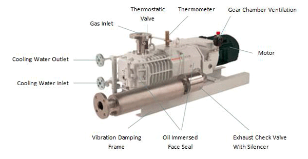
Several accessories are commonly found on dry pumps (Fig. 5) and include:
- Dust separator provided on the pump inlet to remove contaminants from the pumped gas stream prior to reaching the pump. The separator is designed to remove dust and other contaminants with a size greater than the rotor/stator clearance as particles smaller than this can be harmlessly passed through the pump. A typical separator design uses a polyester filter with a 5 micron particulate capture capacity.
- Exhaust silencer since the pump outlet is exposed to the factory atmosphere, considerable noise can be generated by the pump. This is mitigated by the use of an exhaust silencer located on the pump outlet. The silencer is a stainless steel muffler that reduces the noise to acceptable levels. Sound levels of less than 75 dB(a) are typical with the use of an exhaust silencer.
- Exhaust check valve to protect the pump against condensate and particles returning from the exhaust, a check valve is located on the outlet. The valve is constructed of stainless steel, and positioned between the pump and the silencer.

Summary
Dry pumps represent a technology that is of interest to many heat treaters as they strive to increase performance and minimize cost and downtime. The advantages of these pumps are comparable to their oil sealed rotary vane cousins, and in certain applications, offer distinct advantages.
References
1. Herring, Daniel H., Vacuum Heat Treatment, BNP Media, 2012.
2. Precision Plus Vacuum Parts, PPlusVac (youtube) video ( https://www.youtube.com/watch?v=8NCjM-GOLJg)
3. The Vacuum Technology Book, Volume I & II, Pfeiffer Vacuum (www.pfeiffer-vacuum.com)
