Today, vacuum technology is utilized in every aspect of thermal processing including such industries as:
- Aeronautics and Astronautics (e.g., solar arrays, linear actuators, turbine blades, gearboxes, landing gear)
- Medical/Dental (e.g., instruments, implants, orthodontic braces)
- Automotive/Truck (e.g., transmission & steering components, catalytic converters, fasteners)
- Commercial heat treatment
- Food & Beverage (e.g., rotary cutters, knives, blades)
- Household / Personal Usage (e.g., knives, scissors, cookware, and cutlery)
- Military/Defense (e.g., propulsion system components, projectiles)
- Nuclear (e.g., fuel rods, pipe & tube, fasteners)
- Off-road/Racing (e.g., input & output shafts, gears)
- Oil and gas (e.g., drill pipe, tubular products, pump components)
- Additive Manufacturing / Powder Metallurgy / Metal Injection Molding (e.g., medical implants, anti-lock brake components, sensors, firearms, lock parts)
- Tool and Die (e.g., cutters, punches, reamers)
Processes are equally diverse, from brazing of aerospace components and hardening of stainless and tool steel dies to annealing of zirconium tubes and case hardening of power transmission components.
While vacuum furnaces have been manufactured in both semi-continuous (straight-through) and batch configurations), batch vacuum furnaces (in horizontal and vertical configurations) dominate the landscape and are distinguished by the following general features:
- The load is stationary throughout the cycle, being orientated and positioned in the furnace prior to closing the door.
- Each load has its own unique and often preprogrammed recipe to control such process variables as ramp rates (heating & cooling), preheat temperatures and times, final process temperature and time, ultimate vacuum level, partial pressure setpoints and quench gas pressure to name a few.
- Temperature control can be based on either the furnace control thermocouple, load thermocouples or both.
- Vacuum and temperature levels required for each process cycle can be programmed for different part geometries, load configurations, and materials.
- The type of cooling gas and gas pressure can be varied during a given cycle to accommodate the materials being processed or properties (metallurgical, mechanical, etc.) desired.
- Temperature uniformity can be precisely determined at any point in the chamber, which will remain constant unless equipment induced variability is introduced. This testing is accomplished using a stationary survey rack.
- There are no load transfer mechanisms within the hot zone and few to no moving parts.
Vertical Gas Quench Vacuum Furnaces
Vertical single chamber batch vacuum furnaces are quite common throughout the industry. These furnaces have many of the same basic attributes as their horizontal cousins, recognizing that in a vertical unit the load is placed on a bottom platform, which is then raised into the furnace. These vacuum furnaces are equipped with either gas (pressure) quenching or oil quenching, the latter taking place in a separate chamber.
Typical Specifications
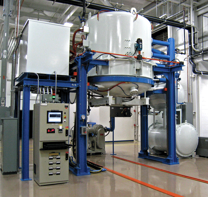
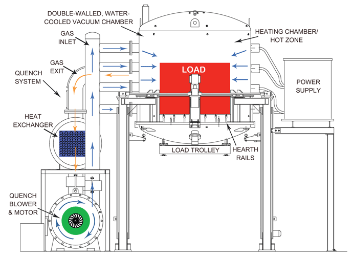
Vertical vacuum furnaces with gas pressure quenching capability (Fig 1) typically operate in the temperature range of 538°C – 1315°C (1000°F – 2400°F). Temperature uniformity meets (or exceeds) AMS 2750 (Pyrometry) specifications. Other typical features are:
- Operating temperatures up to 1315°C (2400°F).
- Ultimate vacuum levels in the 10-6 torr range.
- Modular hot zone designs (for easy maintenance).
- All-graphite and all-metal hot zones
- All-graphite hot zones providing excellent durability.
- All-metal hot zones for ultra-high vacuum and critical cleanliness part processing.
- Curved graphite or molybdenum (pure or lanthanated) strip heating elements
- Selectable gas quench pressures (2 – 10 bar).
- PC-based fully automated controls with HMI interfaces and remote access capability.
- Convection heating capability (optional).
Typical Size Ranges
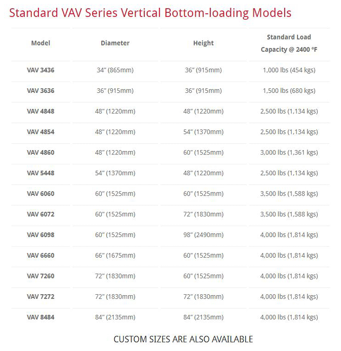
Vertical vacuum furnaces utilizing gas pressure quenching typically process either large, heavy or tall component parts or workloads in which the product is placed multiple layers is advantageous (Fig. 2). There are a number of standard sizes (Table 1) and custom designs (sizes, temperature, hot zone arrangements) available.
Features
A typical vertical bottom-loading vacuum furnace system with gas pressure quenching includes a double-wall vessel, hot zone, gas cooling system, control (operating) system, power supply, and water-cooling system. Briefly, these features can be summarized as follows:
Furnace chamber
The furnace chamber, as well as the upper and lower heads, are a double-wall, water-cooled design, with space between the walls for circulation of coolant. Internal stiffeners are positioned between the walls for added strength. The chamber is equipped with all necessary thermocouple jacks, gauge ports, pumping ports and gas quench entries located for both functionality and easy maintenance access.
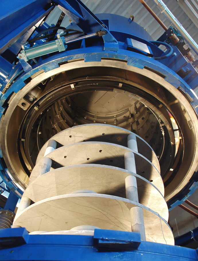
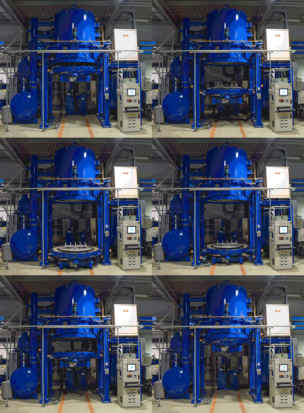
The tank assembly is vertically aligned with a bottom opening load head. The bottom head along with the load is raised and lowered at a constant speed in a smooth continuous motion by ball screw-driven lifting jacks. Once lowered, the bottom head rolls out from beneath the furnace by means of a powered drive assembly to allow complete (360°) access to the load. The vessel is equipped with a powered rotary clamping system to secure the bottom head during processing (Fig. 2). A “ground fault” system is normally supplied to detect if the load or fixtures touch the heating elements during loading or unloading and will stop the elevator to prevent damage.
Hot Zone
Two hot zones configurations are common throughout the industry, namely:
1. Graphite-based Construction
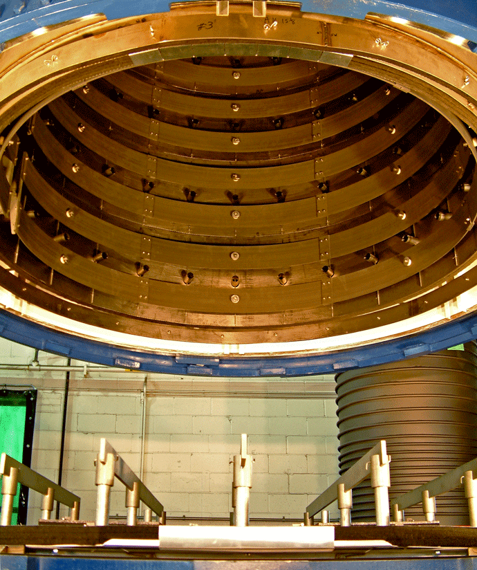
The standard graphite-based insulation package (Fig 3) normally consists of three or more layers of carbon felt with an inner facing of graphite foil bonded carbon composite for added protection and enhanced reflectivity. The heat shield package is supported by a stainless steel support structure that also acts as a manifold to distribute the quenching gas uniformly throughout the workload in a 360º pattern.
2. All-Metal Construction
For ultra-clean processing applications in industries such as aerospace and medical, the use of an all-metal hot zone construction is commonplace. The standard all-metal insulation package consists of two layers of pure molybdenum sheet backed by three layers of stainless steel sheet. The heat shield package is supported by a stainless steel assembly that also acts as a manifold to distribute the quenching gas uniformly throughout the workload.
Vacuum Pumping System
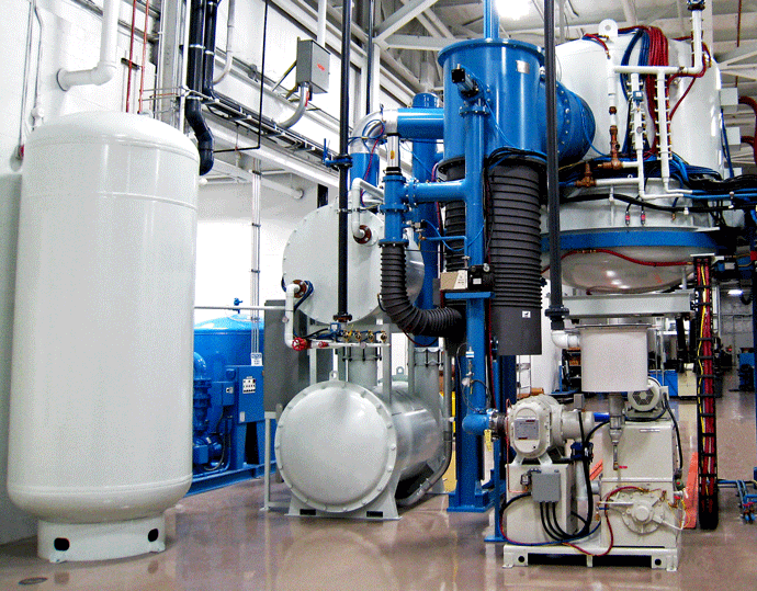
The vacuum pumping system (Fig. 4) will vary depending on the application and the desired operating vacuum level for a given material and process cycle. Many furnaces operate in the “soft vacuum” range (low micron level) where a mechanical pump or mechanical pump/blower type system provides an adequate vacuum level. Other furnaces are built to operate in the “high vacuum range” (typically 10-5 to 10-6 Torr) and utilize a diffusion or turbomolecular pumping system.
In operation, vacuum pumpdown is automatic and interlocked. A holding pump is used to maintain a low pressure on the diffusion pump foreline at all times. This feature, combined with proper timed sequencing of vacuum valves, avoids backstreaming of pump oils. This feature, combined with proper timed sequencing of vacuum valves, avoids backstreaming of pump oils into the chamber.
The basic features of a good vacuum pumping system include:
- Mechanical Pump: Roughing pump and booster combination appropriately sized for furnace volume.
- Diffusion Pump: Varian series complete with a charge of Dow Corning fluid.
- Holding Pump: Rotary vane pump.
- Main, Roughing and Foreline valves: Right angle poppet valve with an electro-pneumatic operation.
- Partial Pressure Capabilities: Partial pressures up to 1 Torr (1000 microns) of inert gas (argon or nitrogen, whichever is used for quenching). Failsafe hydrogen partial pressure system (optional).
Gas Cooling System
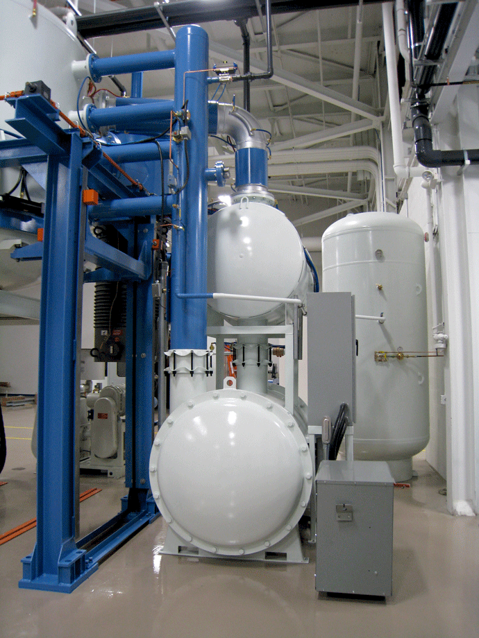
A vertical vacuum furnace with gas quenching capability normally incorporates an external gas recirculating system to cool the inert quench gas used to extract heat from the load at the completion of the heating cycle. Depending on the application, the cooling gas is introduced into the chamber from sub-atmospheric pressure or, for fast quenching, at pressures up to 10 bar. The cooling gas is normally recycled through a heat exchanger and blower system, which can be either internal or external (Fig. 5) to the chamber.
Hot zone power supply
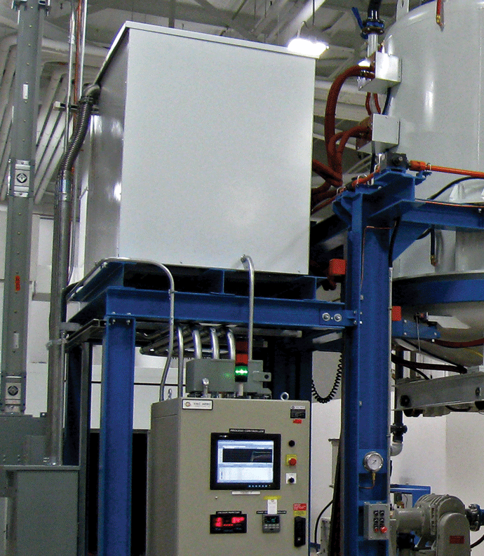
The power supply used to provide power to the heating elements can be of two different types. These commonly are either a silicon controlled rectifier (SCR) or a water-cooled variable reactance transformer (VRT). Each VRT has a 0 – 100% trim control for optimum temperature uniformity in the hot zone. To save floor space, the power pack is often mounted on top of the furnace (Fig. 6).
Instrument control system
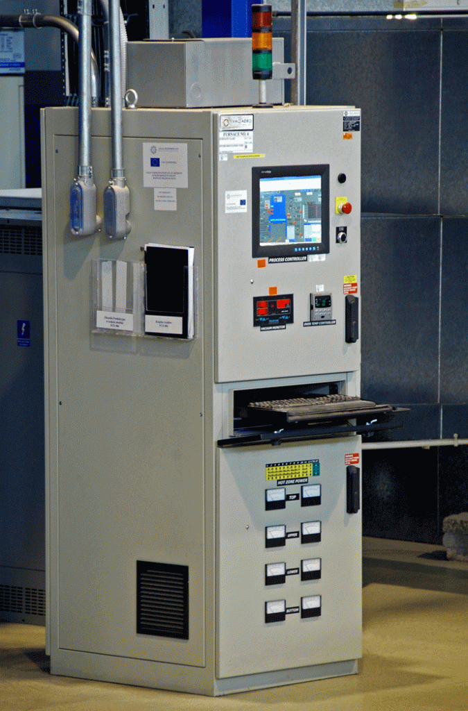
Furnace controls, instruments, and monitoring systems are normally enclosed in a NEMA 12 control cabinet (Fig 7). There are a significant number of choices for instrumentation and controls as well as a variety of HMI, SCADA, and communications strategies. Often the operator will program and monitor furnace operation from the unit while the operation is supervised from a remote location during the cycle.
Hardware components for these furnace controls must be capable of functioning in an “industrial shop” environment. A PLC controls machine functions and furnace temperature, while a programmable controller is used to direct machine operations and furnace temperatures, as well as integrates with software running on a personal computer to provide Supervisory Control and Data Acquisition (SCADA). The operator interface is typically provided through an LCD touch-screen mounted in a control panel. A wide range of standard displays is normally available. Typical features include:
- Compatible with plant-wide SCADA and network integration.
- Process cycle validation.
- Extensive alarm and event management and reporting.
- Temperature control using advanced algorithms, auto-tuning, and multiple PID loops.
- Operator sign-on/sign-off security provides up to 255 control levels to limit operator control of individual items of plant and equipment.
- Enhanced maintenance and troubleshooting management and trending.
Furnace cooling system
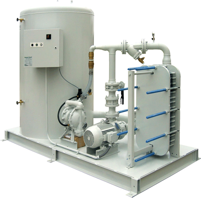
Furnace water cooling system (Fig. 8) consists of a compact manifold containing all necessary pressure regulators, valves, pressure switches and flow regulators with supply and drain hoses and fittings. Dual Loop Cooling Systems are a common option found on these systems.
In Conclusion
Vertical vacuum furnaces with gas pressure quenching capability offer the industry a cost-effective and highly functional design, capable of a processing a wide variety of products under highly controlled conditions to demanding quality standards.
Next Month: We will discuss VAC AERO’s Vertical Oil Quench Vacuum Furnaces and technologies.
