BY JEFF PRITCHARD
High strength steels based on the 43XX series are commonly used for aircraft landing gear components because of their desirable mechanical properties. To achieve optimum mechanical properties, these alloys are usually heat treated by quenching in oil from the hardening temperature, then tempered. This produces a microstructure with high strength and excellent toughness, ideal for applications involving heavy loading and cyclic fatigue. During hardening, internal stresses created from the thermal shock of direct oil quenching almost always cause some degree of distortion in the heat treated component. A final machining allowance is often left on critical dimensional features to compensate for distortion. However, due to the difficulty of machining these alloys in the hardened condition, machining allowances must be minimized.
Many heat treaters have developed hot straightening techniques to reduce quench distortion. However, these techniques are very labour intensive and often involve expensive tooling. In the current environment of cost and lead-time reduction, reducing distortion during thermal processing has become a primary objective for heat treaters of landing gear components.
Interrupted quenching techniques such as ausbay quenching offer good potential for reducing quench distortion. Shown in Figure 1 is an isothermal transformation (I-T) diagram for 300M (4340M) alloy, the most commonly used steel for ultra high strength aircraft applications. The I-T diagram illustrates the microstructural transformations the steel undergoes over time at constant temperature. Superimposed on this diagram is a curve depicting the cooling rate required for successful ausbay quenching.
Ausbay quenching involves the hardening of the steel by first rapidly cooling from the austenitizing temperature to an intermediate temperature above that where martensitic transformation begins. This intermediate temperature range corresponds to the austenite “bay” region of the cooling curve. Cooling from the austenitizing temperature to the ausbay region must be sufficiently fast to avoid the “nose” of the cooling curve or the formation of undesirable products of austenitic decomposition will take place. The temperature of the load is allowed to stabilize in the ausbay region to ensure that any residual thermal gradient from cooling is reduced. After stabilizing, the load is quenched through the martensitic transformation range to ambient temperature.
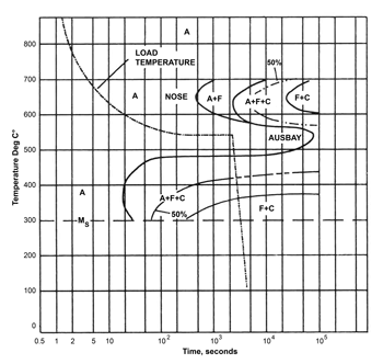
By interrupting the cooling process, the ausbay quenching technique reduces the internal stresses that are created within the material due to thermal shock. Cooling the load quickly to the stabilizing temperature in the ausbay region ensures that an austenitic structure is maintained. Subsequent quenching from this lower ausbay temperature reduces thermal shock compared to the normal practice of direct quenching from the usual hardening temperature.
This results in a lower level of internal stresses with corresponding improvements in dimensional stability of the heat treated part. It should be noted that only certain steel compositions can be successfully hardened by ausbay quenching.
These compositions contain sufficient amounts of alloying elements to ensure that cooling to the ausbay region can be accomplished on a practical basis without intersecting the nose of the I-T curve.
Traditionally, most ausbay quenching processes have been performed using salt baths. Typically, the load is heated in one salt bath maintained at the hardening temperature. After a soak period sufficient to ensure complete austenitic transformation, the load is quickly transferred to a second salt bath held at an intermediate temperature within the ausbay range.
After the temperature of the load stabilizes in the second salt bath, it can be removed and quenched in oil. Though it offers certain benefits, salt bath heat treating presents a number of environmental concerns.
The process generates significant amounts of undesirable emissions, including corrosive fumes and contaminated rinse water. Copper plating must also be used to protect part surfaces from detrimental changes in surface chemistry during salt bath heat treating.
The plating is stripped with solutions containing cyanide that are difficult and expensive to dispose of. Furthermore, there is a risk that any entrapped salt residues may cause corrosion of the heat treated part when exposed to moisture in service. Because of these problems, alternatives to salt bath heat treating have been actively sought.
Vacuum Furnace Aubsay Quenching
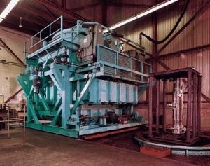
With advances in computer-based control systems and process capabilities, specially-designed integral oil quench vacuum furnaces can be used for ausbay quenching. The VAC AERO Model VAV 72114 MPOGQ integral oil quench vacuum furnace (Figure 2) was designed specifically for heat treating aircraft landing gear components. Though used mostly for direct oil quenching under vacuum, this furnace is also equipped with an external quench loop for inert gas quenching at pressures up to two bar. The furnace is vertically oriented with a working zone size measuring 1775mm in diameter by 2900mm high and can accommodate gross load weights up to 1200 kg. The control system is logic based and fully automated. A programmable logic controller interfaced with process controllers regulates all mechanical and thermal functions of the furnace. Safety interlocks ensure that all preprogrammed conditions are met before critical process events are activated.
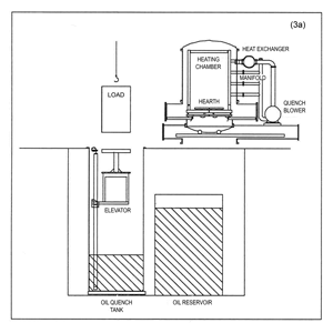
The furnace heating chamber is mounted on a movable gantry. During loading (Figure 3a), the gantry moves aside and the load is placed on an elevator in the quench tank. To avoid contact with the load prior to heating in the vacuum chamber, the quench oil is transferred to a reservoir tank. The elevator lowers the load into the empty quench tank and the heating chamber rolls back into position over the quench tank, then lowers and seals to the quench tank flange. A vacuum seal door and hearth doors within the heating chamber open and the elevator raises the load into the heating chamber (Figure 3b). As the elevator withdraws into the quench tank, the hearth doors close to support the load and the seal door closes to isolate the heating chamber. After the loading sequence is complete the quench oil is pumped back into the quench tank from the reservoir tank.
During processing, the furnace chamber is evacuated to a pressure of approximately 10-2 mb. The oil quench tank is also evacuated to a pressure of approximately 400 mb. When chamber evacuation reaches a certain preset pressure, heating of the load starts. The recommended austenitizing temperature for most high strength steels is usually about 870°C. Heating ramp rates are selected to minimize thermal gradients within the load without creating excessive cycle times. Control of the ramp rate during heating is an important factor in relieving stresses that may have been created during machining of the components being heat treated. During heating, the load is also held at a stand-off temperature of 620°C for a short period of time to further improve temperature uniformity. Maintaining temperature uniformity throughout the cycle is essential to prevent the build up of thermal stresses and to ensure that all sections of the load undergo the microstructural transformations needed to achieve the desired mechanical properties.
 |
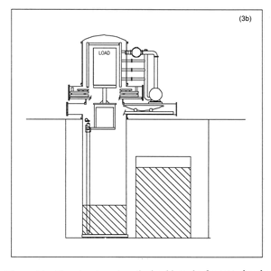 |
| Figure 3a – Loading sequence of integral oil quench vacuum furnace. Heating chamber rolls aside to expose load elevator mounted in quench tank. | Figure 3b – The elevator raises the load into the furnace chamber, then hearth doors and seal door close as the elevator withdraws. Quench oil pumps back into the quench tank from the reservoir. |
 |
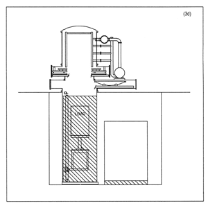 |
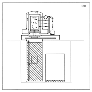
| Figure 3c – Cooling to the ausbay temperature is accomplished by backfilling the furnace chamber with nitrogen and circulating the gas through the furnace quench loop. | Figure 3d – After stabilizing at the ausbay temperature, the furnace doors open, the elevator raises to support the load, then descends quickly into the quench tank to complete the process. |
After the load is soaked for a sufficient period of time at the austenitizing temperature, the ausbay quenching process can begin. The first step in this process is the backfiIling of the furnace chamber with nitrogen gas. Nitrogen is a very economical quench gas with good capacity for heat removal and no detrimental reactivity with the base metal. The chamber is backfilled to a pressure of 400 mb, equalizing it to the pressure in the oil quench tank. During backfill the quench blower is activated. The blower circulates the gas through a manifold, plenum and series of quench nozzles located 360° around the circumference of the load. Hot gas exits the chamber and passes through a heat exchanger where it is cooled before being recirculated by the blower through the load (Figure 3c).
Cooling by gas quenching continues until the load has reached a temperature of about 537°C, in the middle of the ausbay region. The rate of cooling during the gas quenching stage is carefully controlled so that it is fast enough to avoid the nose of the cooling curve but not so fast that the load is cooled below the required ausbay temperature. The amount of quench gas blown through the load is regulated by a damping valve in the manifold. Normally open for maximum cooling rate, this valve will begin to close if the ausbay temperature is at risk of being undershot. As the nose of the cooling curve is passed, heating element power is also increased to further slow the cooling rate. Both heating and quench gas flow are automatically controlled through the microprocessors in the furnace control system.
When the ausbay temperature is reached, the damping valve is fully closed and the gas quench stage of the process is complete. Sufficient power is applied to the furnace heating elements to maintain the load at 537°C. After a reasonable soak period, the temperature of the load is stabilized and the oil quench stage begins. First, the vacuum seal door is opened and the quench elevator is raised to a point where it again supports the weight of the load. The hearth doors are then opened and the elevator and load rapidly descend into the quench tank (Figure 3d). Power to the heating elements is maintained during oil quenching to ensure that the load remains at the ausbay temperature until immersion in the quench oil. After the load is lowered into the quench tank, power to the heating elements is shut off and the vacuum and hearth doors are closed. The quench blower is then re-activated to cool the heating chamber to ambient temperature.
The quench tank contains more than 40,000 litres of quench oil. Oil temperature is regulated by heaters and coolers to ensure sufficient quench speed while preventing excessive thermal shock. Careful monitoring of quench oil conditions is another important factor in distortion control.
Practical Applications
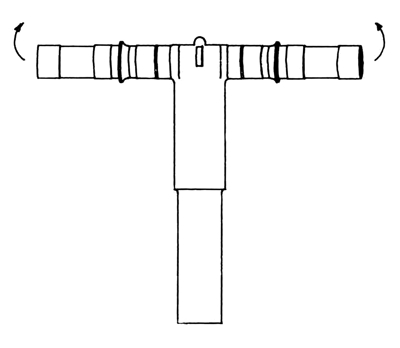
Case Study 1: Main Landing Gear Piston. A piston typical of those used in the main landing gear of a large commercial aircraft is illustrated in Figure 4. Manufactured from 300M material, this piston has a barrel height of approximately 1350mm and measures about 1000mm wide across the axle. Both barrel and axle are tubular in design with section thicknesses ranging from a minimum of 2.5mm throughout most of the tube wall to 20mm where barrel and axle meet. The material is heat treated to an ultimate tensile strength of 19,700 – 21,100 kg/cm² (280 – 300 ksi).
During hardening, the piston is hung in a vertical position. Past experience has shown that hanging vertically produces far less quench distortion than processing in a standing or horizontal orientation. Despite these fixturing precautions, distortion of the axle section by upward deflection during quenching is an inherent outcome of the hardening cycle. In a sample of twenty pistons subject to direct oil quenching, distortion of the right and left hand sides of the axle averaged .58mm from the centerline. Fifteen of the twenty pistons in the sample exceeded the allowable axle distortion limit of .50mm and required hot straightening for dimensional recovery.
 |
 |
|
Figure 4 – Schematic illustration of Main Landing Gear Piston. Arrows show direction of axle distortion occurring during quench
|
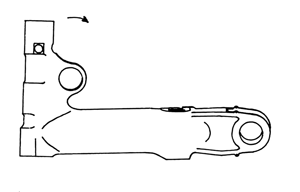
Figure 5 – Schematic illustration of Main Fitting showing direction of distortion of trunnion arm during quench
|
A second sample of twenty pistons was hardened using the ausbay quenching technique. Though upward deflection of both right and left hand sides of the axle again occurred, the distortion was much less than experienced with direct oil quenching. With ausbay quenching, axle distortion averaged only .28mm and none of the twenty pistons exceeded the allowable axle distortion limit. Final inspection of each load confirmed that mechanical properties achieved by ausbay quenching met all specification requirements and were very similar to those measured in samples hardened by direct oil quenching.
Case Study 2: Main Fitting. A second comparison of direct oil quenching versus ausbay quenching was performed on a sample of Main Fittings, a component of the landing gear from a smaller regional jet aircraft. The fitting is again manufactured from 300M material and requires heat treatment to the same mechanical properties as the piston discussed earlier. During the hardening cycle, the fitting is fixtured in a horizontal position as shown in Figure 5. In this case, the most serious distortion occurs when the trunnion arm of the fitting deflects inward during oil quenching. In direct oil quenching of twenty fittings, deflection of the trunnion arm from the centerline averaged .68mm, well above the allowable limit of .50mm. When ausbay quenching was used for hardening of these parts, trunnion arm distortion was reduced to an average of only .17mm. Again, all required mechanical properties were met.
In these two examples, ausbay quenching reduced average quench related distortion by more than 50% compared to direct oil quenching without any loss in mechanical properties. These improvements in distortion yielded significant savings in hot straightening labour and tooling.
High Pressure Gas Quenching
Many aerospace heat treating specifications now permit vacuum hardening of limited section thicknesses of certain high strength steels by gas quenching at pressures of 5 bar or higher. The development of high pressure gas quenching was based on the principle that the denser the cooling medium, the more heat will be extracted from the load. By pressurizing, the quench gas becomes more dense and has improved heat transfer properties. In addition to the pressure of the quench gas, the cooling efficiency of the system is influenced by other factors such as the type of quench gas used, the velocity of the gas and design factors related to the size and shape of the chamber in which the quenching is taking place.
In terms of distortion control, it is widely assumed that because gas quenching creates less thermal shock than oil quenching it should produce less quench-related distortion. In 1998, VAC AERO commissioned a large bottom-loading vacuum gas quench furnace with a 10 bar pressure quenching capability. A number of trials were performed on different components to compare distortion caused by oil quenching to that caused by high pressure gas quenching. Surprisingly, it was determined that for many components, distortion caused by gas quenching was greater than caused by oil quenching. With gas quenching, cooling rate can vary significantly at different points on the surface of the component. Differential cooling rates within an individual component can cause stresses that lead to distortion. Oil quenching provides more uniform cooling as all surfaces of the load are quickly enveloped by the quenching medium.
Conclusions
Practical studies confirm the benefits of ausbay quenching in reducing distortion during hardening of complex components. While the use of ausbay quenching is limited to certain alloy compositions, many of the steels used in high strength applications can be successfully hardened by this technique. The use of vacuum furnaces for ausbay quenching is a relatively recent advance made possible by microprocessor-based furnace control systems and specialized equipment design. By combining gas and oil quenching in an interrupted quenching process, high strength steels can be heat treated to achieve full mechanical properties while minimizing quench distortion. Ausbay quenching reduces heat treating costs by avoiding labour and tooling expenses associated with hot straightening. The use of vacuum furnaces for performing this process provides further cost savings over older heat treating technologies by eliminating several expensive environmental concerns.
