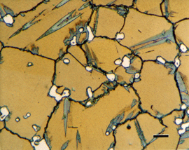
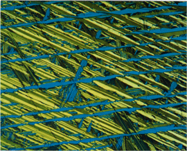
For most of its history, metallographic observations have been largely qualitative in nature. The structure might be described as being relatively coarse or fine, or layered, or uniform. Particles might be labeled as globular or spheroidal, lamellar, acicular, or blocky. Microstructures were single-phase or duplex, and so forth.
Forty some years ago when I entered industry, chart ratings and visual examinations were the main approach toward quantitation. I can well remember the mill metallographers looking at spheroidized carbide tool steel structures and stating that it was, for example, 90% spheroidized (many raters would never say 100%, just as some teachers would never grade an essay at 100%!) or that it was 60% spheroidized and 40% lamellar tending to spheroidize. Or, without looking at the chart (a seasoned rater never did!), they would pronounce that the grain size was, for example, 100% 6 to 8 or perhaps 70% 8 and 30% 3 to 5 if it was duplex in appearance.
As a novice metallurgist, I was quite impressed by these pronouncements and tried to repeat the practice on my own. But, I found myself unable to repeat such ratings, if done several weeks apart, unless I made my estimates very broad. Later, I tried submitting the same specimens to different metallographers or to the same person at different times. I quickly learned that their repeatability/reproducibility wasn’t that much better than mine. (Don’t let a mill metallographer know that you are checking him/her!)
The greatest mystery to me, however, was inclusion chart ratings. I was very impressed that they could scan the 160 square mm area in a few minutes and, without taking any notes, jot down worst-field ratings. Absolute black magic! I never could do this. I had to use a scale and measure stringer lengths or count inclusions when I saw a field that looked like it had a high inclusion content. And I had to keep notes. But I was a college graduate, and some of these men did not complete high school! Was I overly dense?
Naturally, I tried testing their ability to reproduce test results, and I found out that maybe I wasn’t as slow so I thought. They didn’t do that well reproducing their own results. Later, when I became active with ASTM Committee E-4, I found that inclusion ratings on round-robins, which had been tried numerous times, were notoriously non-reproducible. Well, that was good for soothing my shattered ego, but it did not solve my problems of describing structures.
 |
|
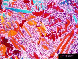
Image of a specimen of Cu-20% Sn, heated to 930F and water quenched, etched with Klemm’s III at 500X in polarized light plus sensitive tint
|
I Discover Stereology
In the early 1970’s, I came across some articles and a book, Quantitative Stereology, written by the late Ervin E. Underwood. This was the beginning of a lifelong interest in quantifying microstructures and a long time friendship with a fascinating gentleman, Erv Underwood.
Stereology is used to quantify matrix microstructures, as opposed to standard metrology techniques for measuring case depth, plating thickness, or particle size. Microstructural measurements are made on a two-dimensional plane-of-polish through a three-dimensional opaque metal. Stereology converts these 2-D measurements into 3-D estimates of microstructural parameters. Most procedures are very simple to use, but there are special considerations for their validity.
Nomenclature
This subject has been hampered by confusion due to the use of different mathematical symbols for the same parameters. To minimize this problem, the International Society for Stereology has promoted a standard nomenclature which is constantly evolving as new approaches are developed. The most basic symbols are:
These symbols can be combined in a number of ways to generate different symbols. For example, Pp represents the point fraction; that is, the fraction of grid points lying in a phase of interest. While A and S seem to be the same, A is for a flat surface while S is for a curved surface. Thus, S represents the grain boundary surface area per unit volume. NA is the number of particles per unit area while NV is the number per unit volume.
Phase Proportions
 |
|
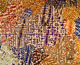
Image of a specimen of a chill cast specimen of Cu – 5% Sn with a dendritic structure at 100X etched with Klemm’s I in polarized light (off crossed position)
|
One of the most common measurements, determination of the amount of phases present, can be done using three different methods. Areal analysis, developed by Delesse in 1848, says that the area percent of a phase on a 2-D plane is equal to its volumetric percent, that is, AA = VV. However, measuring the area of a second phase is very tedious unless it is quite coarse. Lineal analysis, developed by Rosiwal in 1898, says that the lineal fraction of test lines in a phase on the 2-D plane is equal to its volumetric percent, that is, LL = VV. This is relatively easy to determine but still rather tedious.
Starting around 1930, several workers in different fields and countries (e.g., Thomson (1933), Glagolev (1933) and Chalkley (1943)) showed that the percentage of points on a test grid lying in the phase of interest was equal to the volumetric percentage, that is, PP = VV. Of the three methods, this is the most efficient measurement technique; that is, it yields the best precision for the least effort when done manually. The manual point counting technique is described fully in ASTM E 562 (also ISO 9042). Image analyzers use essentially the same procedure; that is, the amount of a phase (usually called the area fraction even if it really is a point fraction) is determined by the number of picture elements or “pixels” in the phase of interest divided by the total number of pixels; i.e., PP, expressed usually as a percentage.
Grain Size
Grain size is perhaps the most commonly performed microstructural measurement, although chart ratings are more commonly done than actual measurements (this is changing). A recent ASTM interlaboratory “round-robin” showed that chart ratings of grain size are biased; that is, the ASTM grain size number is 0.5 to 1 unit too low (See Appendix XI of E 112 – 96 and subsequent editions). No bias existed when planimetric measurements were compared to intercept measurements by the same rater or different raters.
The ASTM grain size number, G, is defined as
n = 2 G-1
where n is the number of grains per square inch at 100X. To convert n to NA (the number of grains per square mm at IX), multiply n by 15.5. The ASTM grain size charts show graded series of grain structures of different types.
The grain size can be measured by the Planimetric Method (developed by Zay Jeffries in 1916 based upon earlier work by Albert Sauveur) or by the Intercept Method (developed by Emil Heyn in 1904). In the Planimetric Method, a count is made of the number of grains completely within a circle of known area plus the number of grains intersected by the circle (half are assumed to be inside the circle) to obtain NA. Then, NA is related to G. This method is slow when done manually because the grains must be marked when counted to obtain an accurate count. If the number of grains that are completely within the circle is high, i.e., >50, the use of a circular area does not introduce much bias. But, as this number decreases, bias will occur because the grains that intersect the circle perimeter are considered to be, on average, half inside and half outside the test area, an assumption which is no longer valid. The great pioneering stereologist, S.A. Saltykov, recommended using a square or rectangular test area. The grains that intersect the four corners are ignored in counting and considered to be 1 grain total. The number of grains per sq. mm. NA, is based upon the sum of the grains completely within the test area, plus one-half of the number that intersect the straight edges plus 1 (for the grains at the 4 corners).
 |
|
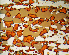
Image of a specimen of 329 duplex stainless steel that was aged producing sigma phase (orange). The matrix is ferrite (colored tannish) and austenite – white
|
In the Intercept Method, either straight lines, curved lines, or circles are placed over the structure and a count is made of either the number of grain boundary intersections, P, or the number of grains intercepted, N, by the line. P (or N) is divided by the true line length, L, to determine PL or NL, the number of intersections or interceptions per unit length (for a single-phased structure). The reciprocal of PL or NL gives the mean lineal intercept length, l, a measure of grain size that can be converted to a G value. The Intercept Method is more efficient than the Planimetric Method yielding acceptable measurement precision (<10% relative accuracy) in much less time. ASTM E 112 contains a complete description of these methods. A major revision of E 112 was completed in 1995. The three-circle intercept method, developed by Halle Abrams, was added to E 112 in 1976. Halle recommended that the magnification be selected to yield, on average, about 100 P or N values per placement, that is, per field. Five such fields would be counted and this would give a relative accuracy of about 10%. An E-4 round-robin showed that counting errors by operators increased as the average P or N per field rose towards 100, or greater. So, the recommendation was changed to select a magnification that yielded, on average, about 40-50 P or N hits per placement and to do at least ten fields to obtain a total P or N of about 500. This still produces a relative accuracy of about 10%, but the higher number of fields sampled yields a better sampling of the grain structure.
Spacings
The spacing between second-phase particles such as carbides or inclusions in steels or between intermetallic particles in aluminum alloys, can affect mechanical properties and formability. A special case is the inter-lamellar spacing of pearlite in high carbon steels (like rail steel) where refinement of the spacing improves both strength and toughness.
Spacings are easily assessed using a simple NL (number of particles in intercepted per unit length of test line) measurement. The mean center-to-center spacing, sometimes called σ, is simply:
σ=1
NL
This is not a nearest-neighbor spacing, but the mean spacing between particles in the test line direction (either placed randomly or in some preferred direction, such as the through-thickness direction).
If the amount of the second phase is determined, for example, by point counting, the mean edge-to-edge spacing, called λ (or the mean free path, MFP), can be calculated by:
λ= 1-PP
NL
where PP is a fraction rather than a percentage. This is a very good structure-sensitive parameter.
By a simple subtraction (σ – λ), we can obtain the mean intercept length of the second phase particles – without measuring any! Furthermore, if we count the number of particles within a known area to obtain NA (including only half of the particles intersected by the field edges), we can determine the average cross sectional area of the particles, Ã, by:
à = PP
NA
where PP is the point fraction (as a fraction, not a %) of the second phase. Thus, the average size of particles can be determined manually without actually measuring the particles. With modern image analyzers, individual measurements of particles are fast and simple. Besides generating average particle dimensions, the distribution of particle sizes can be obtained by feature-specific image analysis.
To determine the interlamellar spacing of pearlite (or of any eutectic or eutectoid constituent), it is common practice to count the number of carbide interceptions with a straight test line perpendicular to the lamellae. However, because the lamellae intersect the surface at different angles, it is better to determine a mean random spacing, σr, than a mean directed spacing, σd. A mean random spacing is obtained by determining NL using randomly oriented test lines (or curved or circular lines). The mean random spacing is easily used to calculate the mean true spacing, σt, by:
σt = σr
2
In the past, the mean directed spacing, σd, was determined for the pearlite colony with the finest spacing, and this was assumed to be the mean true spacing. This is a more valid technique for isothermally formed pearlite than for pearlite formed during continuous cooling. However, the longer you search for the finest colony, the finer the measured colony size! That is, the minimum σd value obtained depends upon the amount of time spent looking for the finest colony, even in isothermally formed pearlite. Any effort spent looking for a “best” or “worst” field condition is strongly influenced by the amount of search time, and the results are neither reproducible nor precise.
Statistics
Other measurements are possible, but the ones described above represent some of the simplest and most useful. Each can be repeated on a number of fields on the plane-of-polish so that a mean and standard deviation can be obtained. The number of fields measured influences the precision of the measurement. Manual measurements are tedious and time-consuming so sampling statistics may be less than desired. Image analysis removes most of the barriers to inadequate sampling.
A good measure of statistical precision is the 95% confidence interval (or confidence limit). This defines a range around the mean value where 95 times out of 100, a subsequently determined mean will fall. A mean volume fraction of 10% ± 2% implies that for 95 of 100 measurements, the mean value will be between 8 and 12%. The 95% confidence interval is determined by:
95% CI = ts
√n
where t is the Student’s t factor (t is a function of the confidence level desired and the number of measurements and can be found in standard textbooks and in some ASTM standards, e.g., E 562, E 1245, and E 1383).
The relative accuracy, RA, of a measurement is determined by:
% RA = 95% CI . 100
X
where X is the mean value. In general, a relative accuracy of 10% or less is considered to be satisfactory.
Sampling
So far, we have discussed measurements on a single plane-of-polish on one specimen. Because we are usually dealing with large quantities of material (such as an entire “heat” of metal or alloy, a large heat treatment lot of bars, forgings, etc., or a large forging or casting), a single specimen may not be representative of the whole quantity. Ideally, random sampling of a large batch would be best, but practical considerations usually rule this out.
In most cases, sampling is done at predetermined convenient locations, such as the extreme ends of a coil, bar, plate, etc., or at locations that will be subject to extensive machining. In some cases, excess metal is added to a forging or casting to provide test material as similar as possible to that of the component. Sampling is often a compromise and is rarely excessive due to cost considerations. However, inadequate sampling or sampling on non-representative material/locations may degrade the value of the measurements.
George Vander Voorthas a background in physical, process and mechanical metallurgy and has been performing metallographic studies for 43 years. He is a long-time member of ASTM Committee E-4 on metallography and has published extensively in metallography and failure analysis. He regularly teaches MEI courses for ASM International and is now doing webinars. He is a consultant for Struers Inc. and will be teaching courses soon for them. He can be reached at 1-847-623-7648, EMAIL: georgevandervoort (AT) yahoo (DOT) com and through his web site: www.georgevandervoort.com
To View a listing of all George’s articles please click here
Read George Vander Voort’s Biography

