Vacaero

Manufacturers of heat treating and brazing vacuum furnaces and controls, complete hot zone and vacuum furnace retrofits, thermal spray coatings, plasma, HVOF and paint coating services.

VAC AERO Service Experience Trust
Canada FrançaisAccessibility |
  • Home
  • Company
  • Vacuum Furnaces
  • Thermal Processing
  • Coatings
  • Service & Support
  • Resources
  • Contact Us
  • Request for Quote

Archives for March 2014

Using Thermal Spray for Repair of Service-Damaged Parts

March 25, 2014 by VAC AERO International

Using Thermal Spray for Repair of Service-Damaged Parts

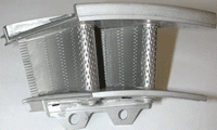
Thermal spray processes like air plasma spray and High-Velocity Oxygen Fuel (HVOF) are usually thought of as being used primarily for applying protective coatings to new parts. While new part applications do indeed constitute the majority of their use, there are also a wide variety of repair techniques that employ thermal spray processes. VAC AERO has been a leader in developing repairs for aircraft structural components and gas turbine engine parts using thermal spray processes. An example of a structural component repair involves a flap track from a popular turboprop aircraft.  As the wing flaps of this aircraft are extended and retracted during landing and take-off, rollers run along the surfaces of a series of components known as flap tracks.

An example of a structural component repair involves a flap track from a popular turboprop aircraft.  As the wing flaps of this aircraft are extended and retracted during landing and take-off, rollers run along the surfaces of a series of components known as flap tracks.  For the original flap track design, the manufacturer applied a nickel-based electroplated coating to protect the roller wear surfaces. However, after a certain period of service, the electro-plated coating was worn away and significant wear also occurred in the base metal substrate beneath. VAC AERO was tasked with coming up with a method of re-building the worn substrate and applying a more durable coating to the wear surfaces. VAC AERO’s solution was to use the HVOF process to apply a tungsten carbide coating over the worn area.  This coating was used for both the restoration of the damaged substrate and as a wear resistant overlay. Because this application requires high bond strength and fatigue resistance, several coating compositions were tested before the ideal candidate emerged. The development of the proper spray parameters also required significant effort to ensure the coating adhered properly, particularly where it “feathered” out at the edges of the overlay.  VAC AERO’s repair technique was subsequently approved by the aircraft manufacturer.

Influence of the Equations Defining HV and HK on Precision

March 9, 2014 by George Vander Voort

Influence of the Equations Defining HV and HK on Precision

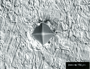
The basic equations defining (see equations 1 and 2) the Knoop (HK) and Vickers (HV) hardness, where the applied force is multiplied by a geometric constant and then divided by the long diagonal squared or the mean diagonal squared, respectively, cause an inherent problem in measuring small indents, that is diagonals ≤20 µm in length.  Figure 1 shows the calculated relationship between the diagonal and load and the resulting hardness for Knoop indents while Figure 2 shows this relationship for Vickers indents. As the test load decreases, and the hardness rises, the slope of the curves for diagonal versus hardness becomes nearly vertical. Hence, in this region, small variations in diagonal measurements will result in large hardness variations.

If we assume that the repeatability of the diagonal measurement by the average user is about ±0.5 µm, which is quite reasonable, and we add and subtract this value from the long diagonal length or the mean diagonal length, we can then calculate two hardness values. The difference between these values is ΔHK and ΔHV, shown in Figures 3 and 4. From these two figures, we can see how the steepness of the slopes shown in Figures 1 and 2 will affect the possible range of obtainable hardness values as a function of the diagonal length and test force for a relatively small measurement imprecision, ±0.5 µm. These figures show that the problem is greater for the Vickers indenter than for the Knoop indenter for the same diagonal length and test force. For the same specimen and the same test force, the long diagonal of the Knoop indent is 2.7 times greater than the mean of the Vickers’ diagonals, as shown in Figure 5.

  • Vacuum Heat Treating: Education & Training
    • News & Announcements
  • Vacuum Technology with The Heat Treat Doctor
  • Vacuum Pump Technology: Education & Training
  • Metallography with George Vander Voort
  • Q’s and A’s
  • “What’s Hot!” Newsletter
  • Glossary Metallurgical Terms
Vertical vacuum furnace specifications
horizontal vacuum furnace specifications
Vacuum Furnaces
Vacuum Furnace Zone Rebuilds
Technical Articles and Resources

Specialists in Vacuum Furnace Technology - High Quality Vacuum Furnace Manufacturer

COMPANY

  • VAC AERO Products & Services
  • Company History
  • Certificates & Approvals
  • Employment Opportunities
  • Values & Commitment
  • Corporate Sponsorship
  • Corporate Brochure
  • Terms & Conditions of Use
  • Privacy Policy

FURNACE MANUFACTURING

  • Horizontal Furnace Specs
  • Vertical Furnace Specs
  • Hot Zones
  • Control Systems
  • Custom Vacuum Furnaces
  • Quality Control
  • Service & Support
  • Furnace Request For Quote (RFQ) Form

THERMAL PROCESSING

  • Ontario – Plant 1
  • Ontario – Plant 2
  • Quebec – Thermal Processing Division
  • Specific Heat Treating & Brazing Approvals
  • Metallurgical Services Matrix

COATINGS

  • Quebec Coatings Division
  • HVOF Spray System
  • Specific Coating Approvals
  • Metallurgical Services Matrix

SERVICES & SUPPORT

  • Furnace Rebuilds & Upgrades
  • Hot Zone Rebuilds
  • Process Controls Upgrades
  • Ordering Parts
  • Field Service
  • Training Seminars

© Copyright 2016 VAC AERO - All rights reserved. Site Map Contact Terms and Conditions Privacy