by George Vander Voort – Carpenter Technology Corp. Reading PA, 19612
Abstract
The paper describes the approach taken in the author’s first metallographical study of plasma sprayed coating. After consideration of the preparation problems known to be associated with porous materials, the coating materials and the substrate material, and coatings in general, literature on metallographic studies of plasma sprayed coatings was identified, obtained and reviewed. A coating section of each type was carefully removed from the substrate, refrigerated in liquid nitrogen, broken and examined with the SEM to reveal the nature and degree of porosity and bonding defects. Specimens were prepared using two different approaches and two variations of one of the approaches. Polishing was conducted using DP-Plan cloths and two different diamond sizes followed by two stages of diamond polishing with conventional cloths and finally using colloidal silica on a vibratory polisher. Vibratory polishing time must be critically controlled for two of the three coatings. Conventional etchants were tried to enhance microstructural detail but the Pepperhoff interference layer method was found to be more useful.
Introduction
When the author was requested to prepare this paper, he had never prepared plasma spray coated specimens for metallographic analysis. As many metallographers are faced with preparing materials for the first time, the author agreed to prepare the paper from that perspective. In most cases when working with a new material, the metallographer first thinks about similar work done in the past where those experiences might prove helpful. The writer had some familiarity with these problems because ASTM Committee E-4 on Metallography had formed two task groups to study these problems and develop standard guides. Discussions with metallographers who work with plasma coated specimens was also useful, although it revealed a diversity of opinions rather than a common consensus. Experience with any type of coated metals will prove to be useful. Also, as plasma spray coatings are quite heterogeneous, experience with polishing composites may prove to be helpful.
Material
The writer was given three plasma sprayed specimens. AMS-7875 (75% CrC balance Ni-20Cr), AMS-7879 (WC-12%Co) and PWA-1337 (Ni-5%Al). although the substrate was not identified, the writer determined that it was a ferritic stainless steel.
Procedure
The writer did not investigate the influence of sectioning technique upon microstructure appearance. Instead all specimens were sectioned with a low-speed diamond saw cutting in the direction from the coating towards the substrate (the opposite direction might damage the coating). Of all the usual cutting procedures available to the metallographer, the low speed saw is the one noted for producing the least damage. Abrasive wheel cutting, with the correct blade and coolant, should be an acceptable procedure but it was not tried by the writer.
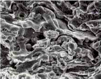
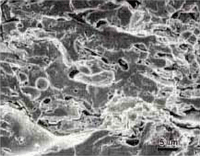
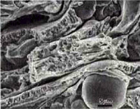
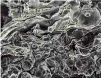
A small section of each coated specimen was further sectioned to remove as much of the base metal substrate as possible. The remaining adherent substrate was carefully ground off using a stationary fine grit SiC paper wet with water. These pieces were refrigerated in liquid nitrogen, placed in a vise and broken by impact Oone of the specimen actually broke during the refrigeration cycle). The pieces were warmed to room temperature, rinsed with alcohol and dried, before examination with the scanning electron microscope. This “cryogenic fracture method” will reveal porosity, delamination or incomplete or complete fusion without any ambiguity as to the influence of cutting and polishing procedures upon the presence or absence of such features.
 |
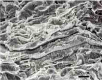 |
| Fig. 1a & b. Secondary electron SEM image of the freeze fracture of the AMS 7875 coating | |
 |
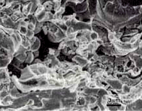 |
| Fig. 2a & b. Secondary electron SEM image of the freeze fracture of the AMS 7879 coating | |
Three different mounting procedures were employed prior to polishing. First, if the writer knew nothing about other people’s work, he would probably mount the specimens using the best procedure for edge retention, electroless nickel plating followed by encapsulation in a compression mounting resin (Resin 5). Because plasma sprayed coating may contain porosity, either interconnected or isolated, and linear separations, most people vacuum infiltrate using epoxy to seal the interconnected porosity open to the surface and provide a mount of the desired size and shape (usually round) for automatic polishing machines. Two of the approaches commonly employed were used. The first was to add Epodye to Caldofix. The Caldofix has good fluidity and forms a hard (for epoxy) mount that does not get tacky when wet with alcohol (one of the most annoying problems with most epoxy mounts). Epodye is useful in that epoxy-filled holes and cracks are vividly revealed using a fluorescent microscope (which the writer does not own). The second approach was to use the Pratt & Whitney (5) technique, that is, Rhodamine B fluorescent dye was added to Stycast 1269 epoxy and vacuum infiltrated into the pores (if present). Porosity or cracks filled with epoxy can be readily observed using fluorescent microscopy or with polarized light if you have a strong Xenon light source. The writer used bright field illumination for examining the coatings. Dark field and Normanski differential interference contrast were tried but were not found to provide any information beyond what was possible with bright field.
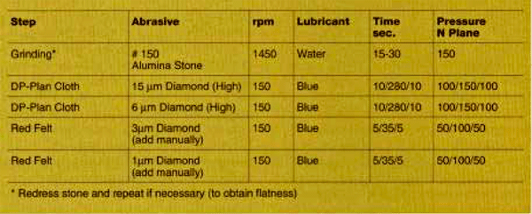
If the writer had been asked to do this work two years ago, he would have polished the specimens using the Petrodisc-M platens and two stages with coarse and fine diamond slurries. However since Struers introduced the DP Plan cloth, we have been using the DP Plan cloths in place of the platens. The platens do a fine job but they do require considerable maintenance. Although polishing with the Petrodisc-M does produce excellent flatness and edge retention, we have obtained even better results with the DP Plan cloth (22). Our polishing procedure for the three plasma sprayed coated specimens, regardless of the mounting media used, is given in Table 1.
Results
The fractured plasma spray coatings were examined with the scanning electron microscope. Figures 1 to 3 show views of the three coatings. These clearly reveal the presence of porosity linear cracks and unmelted particles. It is also quite apparent that the proportion of actual fracture on the surfaces is not very high. The surfaces exhibit fracture of the continuous portion of the coating but substantial regions exhibited as solidified surfaces, that is, areas without fusion between particles.
 |
 |
| Fig. 3. Secondary electron SEM image of the freeze fracture of the PWA 1337 coating | |
Fig. 1 to 3 demonstrate the usefulness of the cryogenic fracture method for revealing the true the true characteristics of the coating. There is considerable debate in the plasma spray community over the presence or absence, of porosity and the true amount of porosity. At one time, tight linear porosity (lack of fusion) was believed to be oxide. It would be quite tedious to define the true volume fraction of porosity using quantitative fractography but the presence, or absence, of porosity should no longer be an issue.
 |
 |
 |
| Fig. 5. Higher magnification views of the coatings shown in Fig. 4 | ||
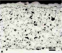
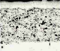
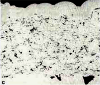
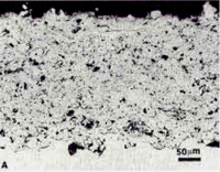
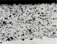
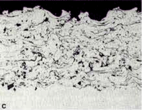
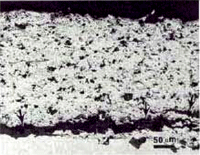
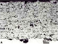
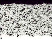
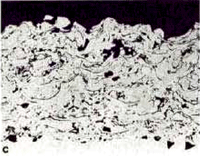
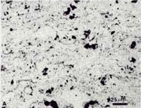
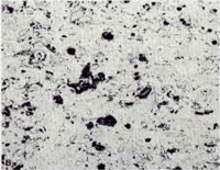
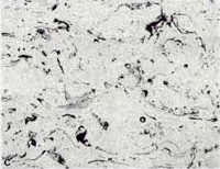
Fig. 4 shows 200X views of the as-polished appearance of the three coatings for the nickel-plated/Resin 5 mounts. Not surprisingly, this mounting system produced the best edge retention and overall flatness but the differences were not great using this polishing method. The porosity (black) is quite evident. The linear lack of fusion regions, most common in the PWA 1337 coating are visible. Contamination at the coating/substrate interface (from shot blasting prior to spraying) is observed on all three specimens. Second-phase particles are clearly visible in the AMS 7879 coating. A grey colored phase is quite evident in the PWA 1337 coating. Unmelted particles are plentiful in both the AMS 7875 and PWA 1337 coatings. Fig. 5 shows each coating at a higher magnification.
 |
 |
 |
| Fig. 7. Higher magnification views of the coatings shown in Fig. 6 | ||
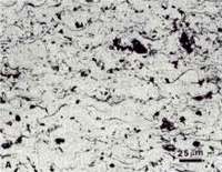
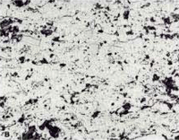
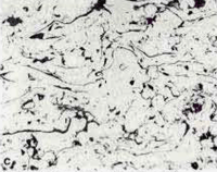
Fig. 6 shows the Epodye/Caldofix mounts after polishing. The edge retention was excellent and the structures are identical. Fig. 7 shows higher magnification views of the microstructure of each coating. Fig. 8 shows a problem that can occur when preparing plasma spray coated specimens. The coating has separated from the matrix during sectioning and epoxy has flowed into the separation during vacuum impregnation (this specimen was cut with an abrasive cut-off saw rather than the low-speed diamond saw used by this writer).
 |
 |
 |
| Fig. 10. Higher magnification views of the coatings shown in Fig. 9 | ||
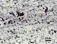
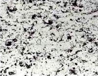
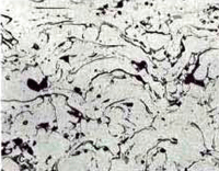
Fig. 9 shows 200X views of the three coatings where Rhodamine B dye was added to the Stycast 1269 epoxy. Edge retention and flatness are very good and the structures are the same as obtained with the two other mounting methods. Figure 10 shows each at 400X magnification.
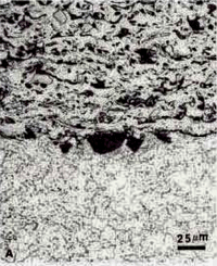
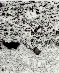
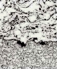
Polishing trials were made using OP-S colloidal silica on a vibratory polisher. For the AMS 7875 and 7879 coatings, polishing longer than about 30 minutes produced overpolishing which exaggerated all of the interfaces. However, for the PWA 1337 coating, times up to 5h were tried and the results were excellent. All of the interfaces were revealed crisply and clearly. A short final polish with colloidal silica was beneficial to all of the structures as the porosity and cracks were more clearly revealed (see Fig. 11). However, for the two AMS coatings, the time must be carefully controlled to avoid overpolishing.
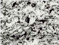
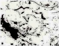
Some etching trials were conducted using standard metallographic etchants, such as Waterless Kallings’s, glyceregia and Murakami’s. None were found to be of any value for enhancing the coating structure, although they did bring up the substrate structure, Fig. 11. Murakami’s reagent (at room temperature) heavily attacked the AMS 7879 coating, although it is widely used for sintered WC-Co hard metals. It was of some value for the AMS 7875 coating but had little effect on the PWA 1337 coating, at least for short etch times at room temperature, fig. 12. While etchants are required to reveal the substrate microstructure, and they do this very well, they do not appear to be helpful for revealing the coating structure, compared to what can be seen in the as-polished condition.
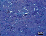
The Pepperhoff interference layer method (23), where a dielectric compound is vacuum deposited onto the polished surface until the layer thickness is great enough to get interference effects, was found to be extremely effective for revealing the structure. ZnSe was utilized and found to be successful, particularly for the PWA 1337 specimen, Figure 13. The pores filled with epoxy, that is, those connected to the surface, were colored light blue while pores not filled with epoxy, or partially filled are black. Unmelted particles and other chemistry variations stand out by color contrast.
Summary
The cryogenic fracture technique was found to be extremely useful in determining the relative soundness of plasma spray coatings. If porosity is present, it will be observed. Other features, such as unmelted particles and linear cracks or delamination, are also apparent. By examining the relative amount of fracture on the surface, one gets an idea of the soundness of the coating.
Three mounting methods were employed and all gave excellent results. Although the electroless nickel plating did not fill in the pores, no problem was encountered in revealing the true porosity with the polishing procedure employed. However, filling in the pores by vacuum impregnation is an excellent approach. Fluorescent dyes are not required if the Pepperhoff interference layer method, or a variation of this technique, is employed as the epoxy filled pores are clearly visible with ordinary bright field illumination. Etchants were not found to be particularly useful, except for revealing the substrate microstructure. More work needs to be done to develop optimum etching methods.
Acknowledgments
I would like to thank Art Geary, Metallography Consulting Services, for supplying me with the three coated specimens and for vacuum infiltrating one set with Stycast and Rhodamine B dye. I would like to thank Judy Loth, Struers USA, for vacuum impregnating a second set of specimens with Caldofix and Epodye. Jesse A. Lesher, Carpenter Technology Corporation, polished all of the specimens.
References
1. G. Elssner and P. Wellner, “Preparation Problems and Phase Identification in Plasma-Sprayed Coatings for High Temperature Applications,” Microstructural Science, Vol. 9, 1981, Elsevier North Holland, New York, pp. 289-297
2. G. A. Blann, “Metallographic Specimen Preparation of Thermally Sprayed Coatings for Microstructural Analysis,” Microstructural Science, Vol. 17, IMS and ASM International, Metals Park, OH, 1989 pp. 139-151
3. G. Elssner et al., “Preparation of Ceramic Sprayed Coating on Metal Substrates”, Practical Metallography, Vol. 27, 1990, pp. 211-230
4. W. J. Brindley and T. A. Leonhardt, “Metallographic Techniques for Evaluation of Thermal Barrier Coatings”, Materials Characterization, Vol. 24, 1990, pp. 93-101
5. A. R. Geary, “Metallographic Evaluation of Thermal Sprayed Coatings”, Microstructural Science, Vol. 19, IMS and ASM International, Materials Park, OH, 1992, pp. 637-650
6. G. A. Blann, “Microetching Techniques for Revealing Thermally Sprayed Coating Microstructures”, Proc. Fourth National Thermal Spray Conf., ASM Int’l.; Materials Park, OH, 1992, pp. 175-186
7. M. Ruckert et al., “Metallographic Preparation of Plasma Sprayed ZrO2 Coatings Sprayed Under Varying Conditions”, Practical Metallography, Vol. 28, 1991, pp. 227-237
8. M. F. Smith et al., “A Comparison of Techniques for the Metallographic Preparation of Thermal Sprayed Samples”, Proc. Fourth National Thermal Spray Conf., ASM International, Materials Park, OH, 1992, pp. 97-104
9. A. Ohmori et al., “The Structure of Plasma-Sprayed Alumina Coating Revealed by Copper Electroplating”, Ibid., pp. 105-113.
10. D. J. Diaz and G. A. Blann, “Thermally Spray Coatings”, ASTM Standardization News, Vol. 19, May 1991, pp. 48-53
11. J. Nerz et al., “Microstructural Evaluation of Tungsten Carbide-Cobalt Coatings”, J. Thermal Spray Technology, Vol. 1, March 1992, pp. 147-152
12. E. Leistner, “Preparation and Evaluation of Thermal Sprayed Coatings”, Practical Metallography, Vol. 30, 1993, pp. 428-440
13. A. Pohl et al., “The Microstructural Analysis of VPS-Coatings”, Practical Metallography, Vol. 31, 1994, pp. 338-348
14. R. Gerhardt and T. R. Grossman, “Characterization of Porosity in Thermal Barrier Coatings”, Ceramic Trans., Vol. 11, 1990, pp. 189-199
15. D. B. Fowler, “A Method for Evaluating Plasma Spray Coating Porosity Content Using Stereological Data Collected by Automatic Image Analysis”, Microstructural Science, Vol 18, IMS and ASM International, Materials Park, OH, 1990, pp. 13-21
16. J. Barsky et al., “Analysis of Porosity of Free-Standing Ceramics Manufactured by Plasma Spraying”, Proc. 1993 National Thermal Spray Conf., ASM International, Materials Park, OH, 1993, pp. 505-511
17. P. M. Treadway and C. C. Berndt, “A Microstructural Index for Pores in Thermal Spray Coatings”, Ibid., pp. 513-517
18. D. B. Fowler et al., “Image Analysis Applied to Thermal Sprayed Coatings”, Proc. Third National Thermal Spray Conf., ASM International, Materials park, OH, 1991 pp. 303-319
19. D. B. Fowler et al., “Inspecting Thermally Sprayed Coatings”, Advanced Materials & Processes, Vol. 38, November 1990, pp. 41-44, 49, 50, 52.
20. D. B. Fowler, “Metallographic Evaluation of Thermally Sprayed Coatings”, ASTM Standardization News, Vol. 19, May 1991, pp. 54-57
21. S. T Bluni and A. R. Marder, “The use of Quantitative Image Analysis for the Characterization of a Thermal Spray Coating”, Proc. Fourth National Thermal Spray Conf., ASM International, Materials Park, OH, 1992, pp. 89-96
22. G. F. Vander Voort and J. A. Lesher, “Preparation of High Alloy Martensitic Steels”, Structure, No. 27, January 1994, pp. 3-8
23. G. F. Vander Voort, Metallography: Principles and Practice, McGraw-Hill Book Co., New York, 1984
George Vander Voort has a background in physical, process and mechanical metallurgy and has been performing metallographic studies for 43 years. He is a long-time member of ASTM Committee E-4 on metallography and has published extensively in metallography and failure analysis. He regularly teaches MEI courses for ASM International and is now doing webinars. He is a consultant for Struers Inc. and will be teaching courses soon for them. He can be reached at 1-847-623-7648, EMAIL: georgevandervoort (AT) yahoo (DOT) com and through his web site: www.georgevandervoort.com
To View a listing of all George’s articles please click here
Read George Vander Voort‘s Biography
|
(191 HV); acetic glyceregia etch; magnification bar is 100 µm long
|

