Abstract
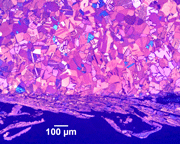 Although some publications have claimed that mechanical specimen preparation is inadequate for producing damage-free specimens for EBSD, this is certainly not true. Our methods have concentrated upon producing the best possible surfaces using an automated grinder-polisher with standard consumable products in a reasonable amount of time and at low cost. Furthermore, these methods are highly reproducible as demonstrated by extensive tests on many metals and alloys from aluminum to zirconium. Success depends first, and foremost, upon limiting cutting damage by using the proper blade and cutter. Next, commence grinding with the finest abrasive that will remove the cutting damage in a reasonable time and make all of the specimens in the holder co-planar. Polishing is done in counter rotation with a low holder rotational speed to keep the cloth as uniformly covered with abrasive and lubricant as possible. The grinding and polishing steps must keep the surface perfectly flat for best results. After the final polish, a general purpose etch can be applied, with the specimens in the holder, to evaluate the success of the preparation and determine what the structure is. Then, remove the etched surface by repeating the final step but with about half the required time. Preparation procedures are influenced by the crystal structure of the specimen. Face-centered cubic specimens will always exhibit more damage from each step than less ductile HCP and BCC metals and alloys.
Introduction
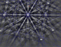
Electron backscattered diffraction (EBSD) is performed with the scanning electron microscope (SEM) to provide a wide range of analytical data; e.g., crystallographic orientation studies, phase identification and grain size measurements. A diffraction pattern can be obtained in much less than a second, but pattern quality is improved by utilizing a longer scan time. Grain mapping requires development of diffraction patterns at each pixel in the field; today, collection rates of 500 or more patterns per second can be achieved which has greatly speeded up this process. The quality of the diffraction pattern, regardless of the collection time, influences the confidence in indexing the diffraction pattern and depends mainly upon the degree of removal of damage in the lattice due to specimen preparation induced damage. Some have claimed that removal of this damage can only be obtained using electrolytic polishing or ion-beam polishing. However, modern mechanical preparation methods, equipment and consumables do yield excellent quality diffraction patterns without reliance upon dangerous electrolytes and the problems and limitations associated with electropolishing and ion-beam polishing. Based upon our EBSD experience, if mechanical preparation produces high quality polarized light images of non-cubic crystal structure elements and alloys (e.g., Sb, Be, Hf, a-Ti, Zn, Zr), or color tint etching of cubic, or non-cubic crystal structure elements or alloys produces high-quality color images, then the surface is free of harmful residual preparation damage and EBSD patterns with high pattern quality indexes will be obtained. Because of the acute angle between the specimen and the electron beam (70 – 74°), exceptional surface flatness is also necessary for best results. Mechanical preparation can easily and safely produce flat, damage-free surfaces for nearly all metals and alloys at a low cost.
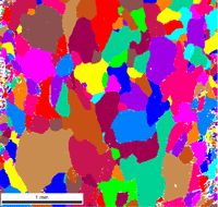
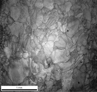
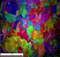
Microstructural image quality in polarized light is dependent upon the elimination of preparation damage and upon the quality of the microscope optics [1]. Consequently, when preparing these metals and alloys, always check the polarized light response of those specimens that will respond to polarized light to verify preparation quality before performing EBSD. For cubic metals, etch first with a general-purpose reagent to confirm the nature of the expected microstructure. Then, repeat the final polishing step and use a color tint etch [1, 2] to verify freedom from damage. EBSD is best performed with an as-polished, non-etched specimen due to the steep angle to the electron beam, as surface roughness can degrade the diffraction pattern. A well-prepared, un-etched specimen will exhibit a good grain-orientation contrast image with a backscattered (or forescattered) electron detector [3]; another good test for freedom from surface damage.
Development of Preparation Methods
Specimen preparation methods for metals and alloys have been developed that yield excellent results using straightforward methods that generally require less than about twenty-five minutes. High-purity metals require more preparation time than alloys. Automated preparation equipment is recommended, as the methods will be performed accurately and reproducibly. Manual (“hand”) preparation cannot produce flatness, phase retention and damage removal as easily as automated processing and is less reproducible. We have always stressed developing the best possible mechanical preparation methods, used with a standard grinder-polisher, such as the Tegra System, before resorting to other final preparation methods, such as a brief electropolish, vibratory polish or ion-beam polish. The vast majority of metals and alloys, and other crystalline materials can be successfully prepared for EBSD with the grinder-polisher.
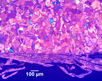 |
| Figure 3. Example of rough swarf due to band saw cutting of annealed cartridge brass tint etched with Klemm’s III reagent |
Because damage removal is so important, it is obvious that each step in the preparation sequence must be designed to impart minimal damage. In almost all cases, the specimen must be sectioned to provide the desired size and plane-of-polish. Sectioning imparts more damage than any other step in the preparation sequence, so it is obvious that cutting damage must be minimized. This is rule number 1 – use the gentlest possible cutting technique. Sectioning is a violent process and it can introduce massive damage if done improperly.
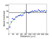
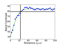
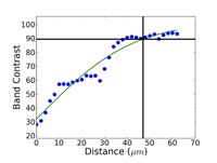
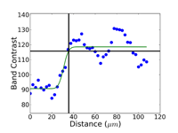
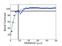
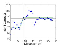
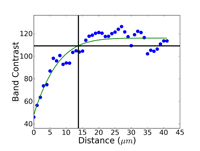
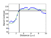
Crystal structure does influence damage depth; face-centered cubic (FCC) metals exhibit greater damage than body-centered cubic (BCC) metals for the same preparation procedure because FCC metals slip more readily than BCC metals. HCP metals and alloys deform by mechanical twining and are more readily damaged than BCC metals and alloys. Use only abrasive blades designed for metallography and are recommended for the specific metal/alloy to be prepared. Flame cutting should never be used for EBSD work as the heat-affected zone can be several cm in depth. Band sawing produces a very rough surface and considerable damage depth and should not be used. A precision saw yields the least damage as the blades are very thin and the applied loads are quite low. The Secotom-10 is an excellent transition between large laboratory cut-off machines and smaller precision saws, as it uses thin wheels like the precision saw, but of larger diameter. Cutting with machines and blades/wheels that introduce minimal damage is the most critical step in generating damage-free metallographic surfaces; this cannot be over-emphasized. Figures 1 and 2 illustrate the depth of damage [4] based upon band contrast data taken parallel to the affected surface at known depths for FCC Cu, BCC Fe and HCP Ti cut with a band saw and with a standard laboratory abrasive cut-off saw using the prescribed blade. The band saw data ignores the rough, irregular swarf at the surface, Figure 3, where the band contrast is zero and starts measurements at the intact surface. It is quite clear that band sawing is far more damaging, even ignoring the rough swarf, than abrasive cutting (which produces no swarf).
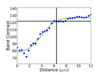
Commence grinding with the finest possible abrasive and surface that will make all of the specimens in the holder co-planar and remove the sectioning damage in reasonable time – this is rule number 2 for obtaining damage-free polished surfaces. Coarse grit-size papers (coarser than 120-grit) can introduce as much damage, sometimes even more, than a laboratory abrasive cut-off saw. Figures 4, 5 and 6 show the damage depths for grinding pure FCC Cu with P80, P220 and P1000 grit SiC abrasive paper lubricated with water. It is clear that the finer the grit size, the shallower is the damage. Of course, the removal rate decreases with decreasing abrasive size. But, for many common metals and alloys, we can utilize a single SiC grinding step after cutting and before starting polishing and get excellent results. Table 1 shows a summary of the damage depths for sectioning and grinding pure Cu, Fe and Ti.
Our preparation methods utilize flat, low-resilience woven cloths or pads that minimize relief problems – rule number 3. To minimize damage, use less aggressive surfaces, such as silk, nylon, polyester or polyurethane. The specimen preparation method must remove all scratches. If scratches are present, damage is below the scratch. Scratch depths produced in grinding and polishing are not uniform. A deep scratch will have deep deformation below it. The preparation method must remove the scratches and the underlying damage in order to obtain high quality EBSD patterns. Use a semi-automatic, or automatic grinder-polisher with the correct load per specimen, rpm of the specimen holder and platen, relative directions of the holder and platen and time. Manual (“hand”) preparation is very tedious and difficult to control. The writer prefers to have the specimen holder rotate at 60 rpm in the opposite direction of the platen. For grinding, the platen rpm should be 240-300, while for polishing, 120-150. With the holder at 60 rpm and the platen at 120-150 rpm for polishing, using counter rotation, the polishing abrasives and lubricants stay on the cloth surface much longer. It is imperative to keep the polishing surface as uniformly coated with abrasive and lubricant during polishing, as possible – rule number 4. If the polishing surface gets dry, then the specimen surface will be rubbed and smeared distorting the lattice. If both holder and platen rotate in the same direction, centrifugal force will throw the abrasive and lubricant off the cloth and down the drain almost as fast as you add them, leading to a dry cloth surface, smearing and poorer diffraction patterns. For some metals, such as Ti, it is necessary to add an attack-polish agent, such as 30% concentration hydrogen peroxide, to the abrasive to get perfect results.
 |
The experiments discussed here cover a wide variety of metals and alloys prepared mechanically using three to seven steps. High-purity metals are more difficult to prepare than commercial alloys, and will require more steps and more time. The methods shown were developed for high-purity specimens and can be simplified for commercial alloys. Table 2 shows a generic preparation practice that will work well for most common commercial alloys. This procedure is not suitable for Ti and its alloys as they must be attack-polished for best results. The EBSD patterns shown below were developed using both the EDAX-TSL and Oxford Instruments HKL systems on a variety of scanning electron microscopes (SEM) using tungsten, LaB6 and field emission electron sources. The plane-of-polish was oriented between 70 and 74° from horizontal, depending upon the system used. The TSL system generates pattern quality indexes, PQI, and the results shown here are the average and 95% confidence limits for 25 randomly selected grains using unetched specimens. The high-purity metallic samples were analyzed using the HKL Channel 5 EBSD system. These patterns were evaluated using the band contrast data, with the average and standard deviation calculated for a number of measurements. Several cast specimens had very large grains, so only a few EBSD patterns could be obtained. The silicon specimen was a single crystal so all patterns were basically identical.
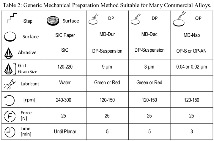 |
| Rotate holder in opposite direction of platen with the holder at 60 rpm. The force listed is per specimen. Use central force loading for best flatness and edge retention. A 1-µm step, similar to the 3-µm step, can be added for more difficult to prepare metals and alloys |
Results
Pure copper is extremely ductile and malleable. Copper and its alloys come in a wide range of compositions, including several variants of nearly pure copper for electrical applications that can be very difficult to prepare damage free. Rough sectioning and grinding practices can easily damage copper and its alloys and the depth of damage can be substantial. Scratch removal, particularly for pure copper and brass alloys, can be difficult, but is possible. If the scratches are not removed, there will be damage beneath. Following the preparation cycle with a brief vibratory polish using colloidal silica is very helpful for scratch and damage removal. Attack polishing additions have been used in the past to improve scratch removal but are not necessary using the contemporary method.
 |
| Rotate holder in opposite direction of platen with the holder at 60 rpm. The force listed is per specimen. Use central force loading for best flatness and edge retention. The 1-µm step is needed for the highest purity iron specimens but is optional for commercial cast irons and steels |
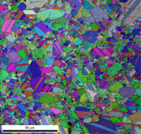
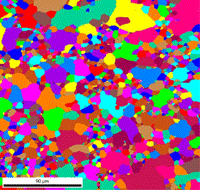
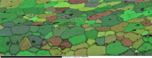
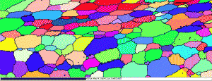
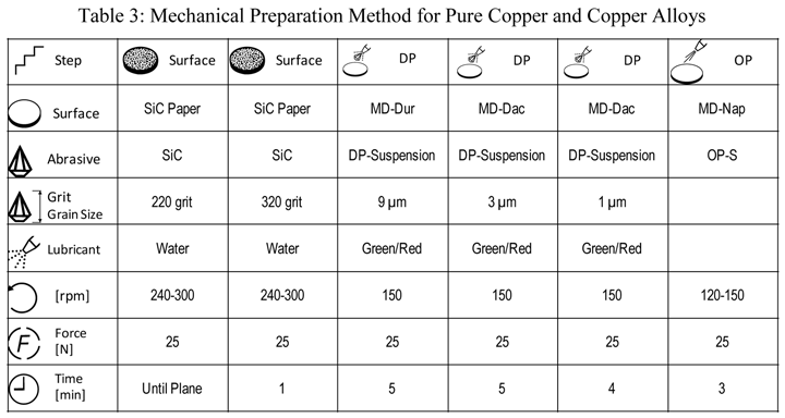
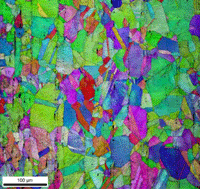
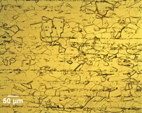
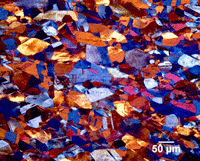
Table 3 lists a six-step method for preparing copper and its alloy. It is always helpful, particularly with alloys that are difficult to prepare damage free, to etch the specimen after the sixth step, and then repeat the sixth step. This reduces damage and gives better EBSD patterns. Figure 7 shows a combined EBSD grain orientation map plus index of quality map for tough-pitch copper (Cu with about 400 ppm oxygen) which reveals the grain structure and annealing twins. Figure 7 also shows the map after twins have been removed. Note that a few twins remained after image processing that will be removed if the boundary angle requirement for a twin is made slightly greater. This specimen was not etched. Figure 8 shows the specimen after etching for comparison. Measurement of grain size in twinned Cu and its alloys is nearly impossible by light microscopy and image analysis due to the inability to reveal all of the grain boundaries and twin boundaries, except by color etching.
 |
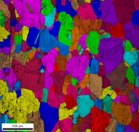 |
| Figure 7: EBSD grain orientation maps plus index of quality maps for wrought, annealed tough-pitch copper; left: map with twins; right: map after twins were removed. | |
 |
 |
|
Figure 8: Microstructure of tough-pitch copper; left: etched with equal parts NH4OH and H2O2 (3% conc.); right: Beraha’s PbS tint etch, polarized light plus sensitive tint illumination.
|
|
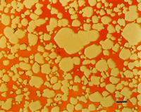
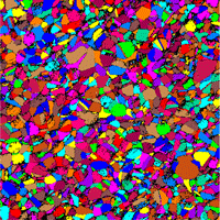
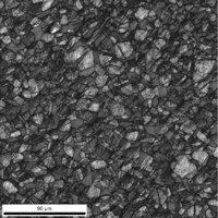
EBSD patterns can be developed for both phases in a two-phase alloy, as long as preparation keeps both phases flat on the plane-of-polish. If relief is present, such that one phase is recessed below the surface, EBSD patterns will not be developed in the recessed phase. As an example, a specimen of Naval Brass, an a-ß brass consisting of Cu – 39.7% Zn – 0.8% Sn, was tested after etching which attacked the ß phase. EBSD patterns could be generated from the a phase, but not from the recessed ß phase. Re-polishing and running the specimen unetched produced excellent results for both a and ß phases as shown in Figure 9. The specimen was prepared in the same manner as used for the cartridge brass specimen.
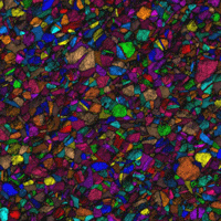
EBSD maps can be made using a number of techniques. Figure 10 shows a grain orientation map, an index of quality map, the combination of these two maps, and a grain-orientation map where the colors have been assigned based on crystal orientation using an inverse pole figure.
| Figure 10: Various EBSD maps for the Naval Brass specimen | |
 |
 |
| Grain-orientation map | Index of quality map |
 |
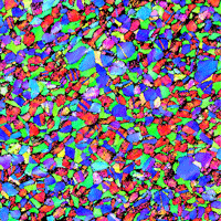 |
| Grain-orientation + Index of quality maps | Inverse pole figure map |
Iron and its alloys are by far the most widely used metals commercially and there are a vast number of commercially-produced alloy compositions covering a vast range of properties and applications. Pure iron is less commonly encountered by metallurgists, but there are electrical applications that employ high-purity iron. Table 4 shows a procedure that can be used to prepare pure iron. This can be simplified, for example by eliminating the 1-µm step, to prepare iron-based alloys, as they are much easier to prepare damage-free for EBSD.
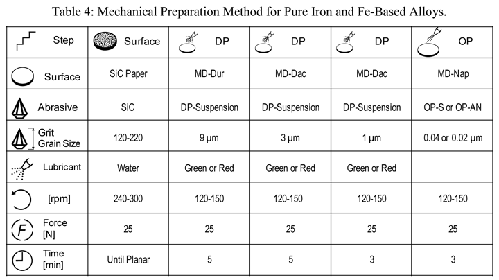
Figure 11 shows an EBSD pattern for cold-worked, non-recrystallized pure (99.98%) iron. That it is deformed and non-recrystallized makes it more difficult to obtain high-quality EBSD patterns, but this has been achieved.
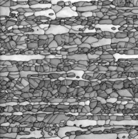
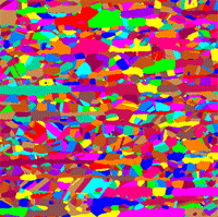
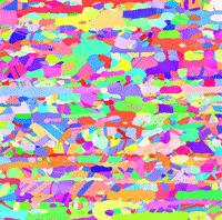
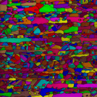
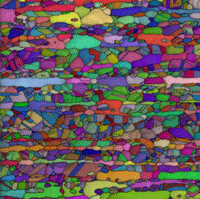
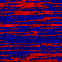
Duplex stainless steels are popular subjects for demonstrating the value of EBSD. Figure 12 shows six maps made using a 2205 duplex stainless steel specimen that was hot worked and solution annealed and then mechanically polished yielding perfect results.
Nickel alloys, particularly superalloys, have been a common EBSD subject. Their preparation is more difficult than iron-based alloys but easier than copper based alloys. Table 5 lists our preferred mechanical preparation method for high-purity nickel. For Ni-based superalloys, we can drop the second SiC step and the 1-µm diamond step and get excellent EBSD results. Figure 13 shows EBSD grain maps for Alloy 625 that was solution annealed at 1000 °C, too low for complete recrystallization.
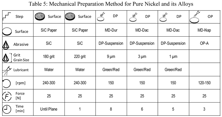 |
| Rotate holder in opposite direction of platen with the holder at 60 rpm. The force listed is per specimen. Use central force loading for best flatness and edge retention. The 1-µm step is needed for the highest purity nickel specimens but is optional for commercial superalloys. One SiC grinding step is adequate for superalloys. |
Refractory metals and alloys have always been difficult to prepare and are of considerable interest in EBSD studies. Niobium and its alloys have been subjects of considerable research interests. Pure Nb is rather challenging to prepare metallographically, but it can be successfully prepared using the method shown in Table 6.
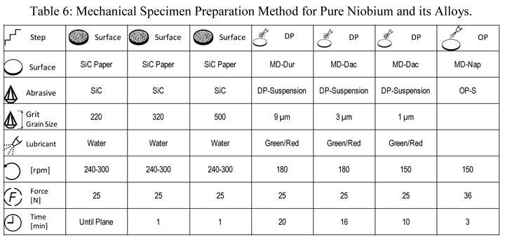 |
| Rotate holder in opposite direction of platen with the holder at 60 rpm. The force listed is per specimen. Use central force loading for best flatness and edge retention. The last step used a 5:1 ratio of OP-S to H2O2 (30% conc.). |
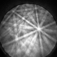
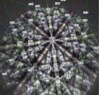
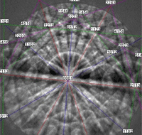
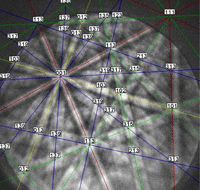
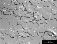
Figure 14 shows an indexed EBSD pattern (one of 25 with an average pattern quality index of 166.2 ± 17.1) and the grain structure of the specimen after etching with a mixed acid reagent.
 |
 |
|
Figure 14: (left) Indexed diffraction pattern for high-purity Nb; (right) microstructure of pure Nb, etched with lactic acid, nitric acid and hydrofluoric acid (6:3:1), Nomarski DIC, 500X.
|
|
Tungsten is another difficult to prepare refractory metal. Table 7 lists a mechanical preparation method that will produce excellent microstructures and EBSD patterns for pure tungsten.
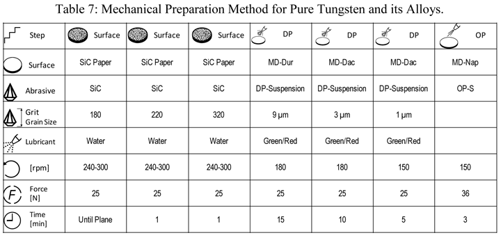 |
| Rotate holder in opposite direction of platen with the holder at 60 rpm. The force listed is per specimen. Use central force loading for best flatness and edge retention. The last step used a 5:1 ratio of OP-S to H2O2 (30% conc.). |
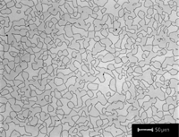
As an example of this method, Figure 15 shows an indexed EBSD pattern from tungsten grains in a P/M W-27% Cu specimen where there is very low solubility for W in Cu and for Cu in W. Figure 15 also shows the microstructure of this specimen.
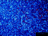
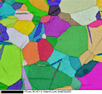
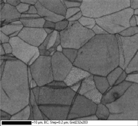
Titanium and its alloys have been widely studied using EBSD. Table 8 shows the procedure that has been applied successfully to hundreds of CP Ti and Ti alloys (a, a-ß, ß and Ti aluminides). In the last step, mix one part 30% concentration hydrogen peroxide with five parts OP-S colloidal silica as an attack polish. For very high-purity Ti, add a 3-µm diamond step, similar to the 9-µm step, but with MD-Dac and 5 minutes time. Figure 16 shows a specimen of commercial purity (CP) titanium polished using the three-step method after making EBSD maps. The first map shows the grains (and mechanical twins) colored according to Euler angles while the second map shows the grain structure and twins revealed using a band contrast map. This was an as hot-rolled bar, not annealed, and the twinning came from deformation that remained after hot working, perhaps from handling or straightening of the bar.
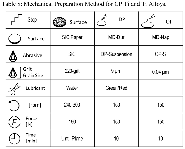 |
| Rotate holder in opposite direction of platen with the holder at 60 rpm. The force listed is per specimen. Use central force loading for best flatness and edge retention. Step 3 uses a 5:1 mix of OP-S to H2O2 (30% conc.). |
 |
 |
|
Figure 16: (left) CP Ti grains colored using Euler angles and (right) same area revealed with a band contrast map (note the mechanical twins in this as-hot rolled bar).
|
|
Perhaps the most difficult refractory metal and alloys to prepare for EBSD have been zirconium and its alloys. Numerous approaches have been tried, using all sorts of procedures, with poor results. Table 9 presents a mechanical preparation method that has yielded excellent grain maps of high-purity Zr and Zr alloys. The SiC paper was coated with paraffin wax before grinding. Final polishing was performed using a 5 to 1 ratio of colloidal silica to hydrogen peroxide (30% conc.). In this experiment, vibratory polishing was used (30 minutes) after the six steps.
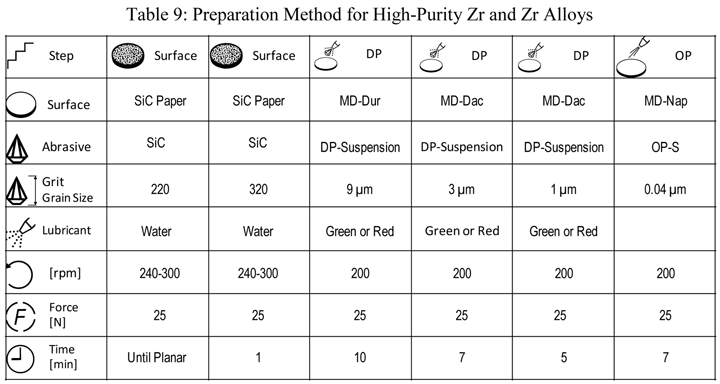 |
| Rotate holder in opposite direction of platen with the holder at 60 rpm. The force listed is per specimen. Use central force loading for best flatness and edge retention. Step 6 uses a 5:1 ratio of OP-S to H2O2 (30% conc.). |
Figure 17 shows two maps of high-purity (99.99%) annealed Zr. The first map was constructed by combining an all Euler grain map with a band contrast map; the second map shows an inverse pole figure map, plus grain boundaries, with the grains with missing pixels (black spots in the first map) filled in. The band contrast averaged 92.34 for the area shown.
Another difficult class of metals to prepare is precious metals. Pure ruthenium, being HCP, is a bit easier to prepare than most of the other FCC precious metals. Table 10 shows a mechanical preparation practice that yields both excellent polarized light response and EBSD patterns.
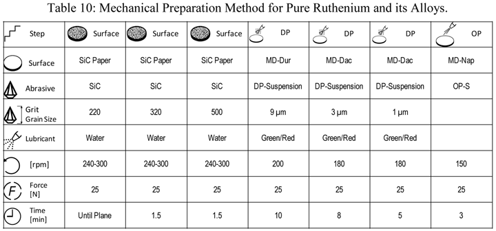 |
| Rotate holder in opposite direction of platen with the holder at 60 rpm. The force listed is per specimen. Use central force loading for best flatness and edge retention. |
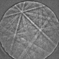
Figure 18 shows an indexed EBSD pattern of pure ruthenium and the microstructure revealed using polarized light with an as-polished specimen.
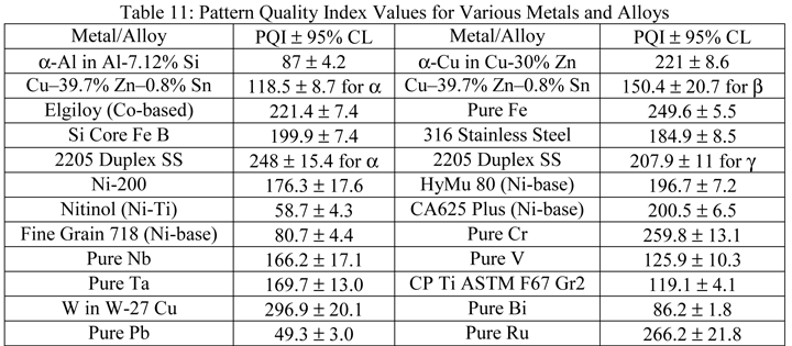
Table 11 summarizes pattern quality indexes (PQI), the average and 95% confidence interval for 25 randomly chosen grains in each specimen, for a number of metals and alloys evaluated, many of which are difficult to prepare. These results clearly show that mechanical specimen preparation, if properly performed, is fully capable of producing damage-free surfaces that yield acceptable EBSD patterns that can be indexed reliably. The Ni-based superalloys (Carpenter’s Custom Age 625 Plus and the fine-grained 718) contained sub-microscopic strengthening phases (the latter also contains copious delta phase) that make the EBSD analyses more difficult. The pure tantalum specimen was a P/M specimen that was not fully dense.
 |
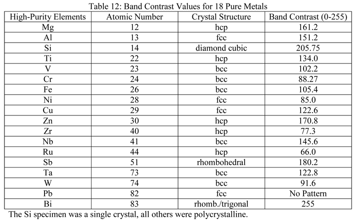
A second set of experiments evaluated the band contrast of eighteen (18) high-purity (generally >99.95%) specimens prepared using methods such as those shown above, or similar methods, usually with five or seven steps (four for pure Ti). These specimens varied from Mg (atomic number 12) to Bi (atomic number 83) and covered the range of metallic crystal structures: body-centered cubic (6), face-centered cubic (4), hexagonal close-packed (5), diamond cubic (1) and rhombohedral/trigonal (2). Table 12 lists the specimens prepared using our standard methods and evaluated by EBSD with the resultant band contrast results.
 |
Specimens of pure Sb, V and Zr were susceptible to SiC embedment, even though the grit size was coarse, e.g., 220- and 320-grit. Hence, grinding was repeated after coating the paper with paraffin wax. Attack polishing was used, mainly with 30% conc. H2O2, for the last step for preparing Cr, Nb, Ti, W and Zr. Colloidal silica was used for the last step, except for preparing Fe (alumina was used) and Mg (water-free alumina was used). Oil-based diamond suspensions (9-, 3- and 1-µm) were used to prepare the high-purity (99.999%) Mg. For the Bi and Pb pure specimens, grinding used four steps: 220-, 320-, 500- and 800-grit SiC paper coated with paraffin wax with low loads, followed by three polishing steps using 5-, 1- and 0.3-µm alumina slurries and a final polish with colloidal silica. All polishing steps used a flocked synthetic cloth. Although the Bi produced an excellent EBSD pattern, none was obtained with the pure Pb specimen. A one-hour vibratory polish with colloidal silica was required to obtain a diffraction pattern for Pb.
A two-minute chemical polish is usually employed after mechanical polishing of Zr; so EBSD was conducted on a second specimen after chemical polishing. Surprisingly, no pattern could be obtained on the chemically polished specimen. Chemical polishing improved the polarized light response but introduced grain faceting (excessive relief). It has been reported that using heavy pressure with the same chemical polish minimized relief and yielded good EBSD grain maps. The result for pure Zr in Table 12 was obtained on the same specimen as illustrated above in Figure 16, but after an earlier preparation attempt with a less effective preparation method than presented in Table 9. The average band contrast for the high-purity Zr specimen using the method in Table 9 was 92.34 and ~90% of the pixels produced indexable diffraction patterns. For the results published in Table 12, the average band contrast was 77.3 and only about 20% of the pixels yielded indexable diffraction patterns.
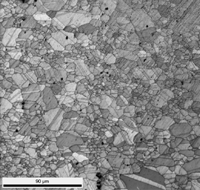
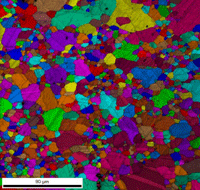
As a final example, a specimen of very high purity polycrystalline silicon (99.99998%) was prepared and analyzed by EBSD. It was very coarse grained and contained what appeared to be annealing twins (Si has an A4 diamond cubic grain structure based on two interpenetrating FCC lattices). Figure 19a shows an EBSD grain map over several combined fields. Analysis of the misorientation across the twin boundaries verified that they were twins. Figure 18b 9shows the region after the twins were removed. Figure 19c shows a montage of the microstructure after etching with aqueous 75% NaOH, again revealing the annealing twins.
Conclusions
Mechanical specimen preparation, when properly performed using modern automated preparation equipment is capable of preparing damage-free, flat surfaces for nearly all metals and alloys within a reasonable time frame and at a reasonable cost. To get good EBSD results, cutting of specimens must be done with the least damaging technique, using a precision saw or a laboratory abrasive saw, with the correct blade. Never use more damaging techniques, such as a band saw, power hack saw or flame cutting. Use the thinnest possible blade with proper coolant. Then, commence grinding with the finest abrasive that will get all specimens in the holder co-planar and remove the cutting damage within a reasonable amount of time. Avoid using grits coarser than 120. Always consider what the crystal structure of the metal or alloy is before setting up the practice. FCC metals and alloys will always exhibit a greater damage depth than less ductile HCP and BCC metals. For the rough and fine polishing steps, use flat, low-resilience cloths (such as silk, nylon, satin, polyester and synthetics) to maintain specimen flatness. Less aggressive cloths are preferred as they introduce less damage. Extra time can be added to achieve the desired total removal depth. Keep the surface as uniformly covered with abrasive and lubricant as possible throughout each step to avoid smearing. This requires use of a low holder speed (e.g., 60 rpm) rotating in the direction opposite to the platen. Use a lubricant that actually has lubricity – petroleum based products, not alcohol-based products. Use the correct load, especially in the final preparation step, which may utilize a low nap cloth, to minimize relief.
After polishing, clean the specimens in the holder and lightly etch them with a general purpose reagent to determine the nature of the microstructure and verify polishing quality. If the alloy has a non-cubic crystal structure, polarized light can be used. The lower the residual damage depth, the better the polarized light image quality – and the better the EBSD response. If a specimen can be color etched, good color results also verify freedom from damage and predict good EBSD results. Remove the etch by repeating the last step for about half of the original time. For some metals, such as refractory alloys and precious metals, an attack polish agent may be added to the abrasive to aid in damage removal. There may be some metals and alloys, such as Pb, where the mechanical preparation results are still marginal or inadequate, and a follow up with a light electropolish, a vibratory polish or ion-beam polish is required. But, for the vast majority of commercial alloys, mechanical preparation is highly satisfactory, as demonstrated here. The logical approach to EBSD preparation is to do the best possible preparation with an automated grinder-polisher and when that is inadequate, follow it with alternative approaches.
References
George Vander Voort has a background in physical, process and mechanical metallurgy and has been performing metallographic studies for 43 years. He is a long-time member of ASTM Committee E-4 on metallography and has published extensively in metallography and failure analysis. He regularly teaches MEI courses for ASM International and is now doing webinars. He is a consultant for Struers Inc. and will be teaching courses soon for them. He can be reached at 1-847-623-7648, EMAIL: georgevandervoort (AT) yahoo (DOT) com and through his web site: www.georgevandervoort.com
To View a listing of all George’s articles please click here
Read George Vander Voort’s Biography

