Introduction
 Although the fundamental relationships for stereology, the foundation of quantitative metallography, have been known for some time, implementation of these concepts has been restricted when performed manually due to the tremendous effort required. Further, while humans are quite good with pattern recognition, as in the identification of complex structures, they are less satisfactory for repetitive counting. Many years ago, George Moore (1) and members of ASTM Committee E-4 on Metallography conducted a simple counting experiment. About 400 people were asked to count the number of times the letter “e” appeared in a paragraph without striking out the letters as they counted. The correct answer was obtained by only 3.8% of the people. Results were not Gaussian, however, as only 4.3% had higher values while 92% had lower values, some much lower. The standard deviation was 12.28. This experiment revealed a basic problem with manual ratings. In this case the subject was one very familiar to the test subjects, yet only 3.8% obtained the correct count. What degree of counting accuracy can be expected when the subject is less familiar, such as microstructural features? Image analyzers, on the other hand, are quite good at counting but not as competent at recognizing features of interest. Fortunately, there has been tremendous progress in the development of powerful, user-friendly image analyzers over the past two decades.
Chart methods for rating microstructures have been used for many years to evaluate microstructures, chiefly for conformance to specifications. At this time, true quantitative procedures are replacing chart methods for such purposes and they are gaining usage in quality control and research studies. Examples of the applications of stereological measurements have been reviewed by Underwood (2).
Basically, two types of measurements of microstructures are made. The first group includes measurements of depths ? i.e., depth of decarburization, depth of surface hardening, or thickness of coatings or platings. These measurements are made at a specific location (the surface) and may be subject to considerable variation. To obtain reproducible data, these surface conditions must be measured at a number of positions on a given specimen and on several specimens if the material being sampled is rather large. Standard metrology methods are used and these can be automated. Metrology methods are also used for individual feature analysis of particle size and shape measurement.
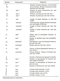
| Table I. ISS Nomenclature for Stereological Measurements (Underwood, 3) |
 |
| * Arbitrarily shown in millimeters |
The second group of measurements belongs to the field referred to as stereology. This is the body of measurements that describe the relationships between measurements made on the two-dimensional plane of polish and the characteristics of the three-dimensional microstructural features sampled. To facilitate communications, the International Society for Stereology (ISS) has proposed a standard system of notation, as shown in Table 1 (3). This table lists the most commonly used notations; there are other, newly developed procedures where the notation has not been standardized.
These measurements can be made manually with the aid of templates outlining a fixed field area, systems of straight or curved lines of known length, or a number of systematically spaced points. The simple counting measurements, PP, PL, NL, PA and NA, are most important and are easily made. These measurements are useful by themselves and can be utilized to derive other important relationships. These measurements can also be made using semi-automatic tracing tablets or automatic image analyzers.
In this chapter, the basic rules of stereology are described with emphasis on how these procedures are applied manually. Other chapters describe how these ideas can be implemented using image analysis. Image analysis users should understand these principles before using them. When developing a new measurement routine, it is good practice to compare image analysis data with data developed manually. It is easy to make a mistake in setting up a measurement routine and one needs a check against such occurrences.
SAMPLING
Sampling of the material is an important consideration as the measurement results must be representative of the material. Ideally, random sampling would be best, but this can rarely be performed, except for small parts like fasteners where a specific number of fasteners can be drawn from a production lot at random. However, with a large forging or casting, it is generally impossible to select specimens at random from the product mass and test specimens are generally taken from excess material added to the bulk for such purposes. For a casting, it may be possible to trepan sections at locations that will undergo machining at some later step. The practice of casting a small “keel block” for test specimens may produce results markedly different than would be obtained from the casting if there is a large difference in size, solidification and cooling rates. After the specimens are obtained, there is still a sampling problem, particularly in wrought material. Microstructural measurements made on a plane parallel to the deformation axis will often be quite different from those taken on a plane perpendicular to the deformation axis, especially for features such as nonmetallic inclusions. In such cases, the practice is to compare results on similarly oriented planes. Few people have the time to measure the microstructural feature of interest on the three primary planes in a flat product, such as plate or sheet, so that the true three-dimensional nature of the structure can be determined except, perhaps, in research studies.
The sampling plan must also specify the number of specimens to be tested. In practice, the number of specimens chosen is a compromise between minimizing testing cost and the desire to perform adequate testing to characterize the lot. Excessive testing is rare. Inadequate sampling is more likely due to physical constraints with some components and a desire to control testing costs. In the case of inclusion ratings, the testing plan was established years ago by the chart method, ASTM E 45. The procedure was to sample billets at locations representing the top and bottom, or top, middle and bottom, of the first, middle and last ingots on a heat. The plane of polish is longitudinal (parallel to the hot working axis) at the mid-thickness location. This yields six or nine specimens. The area examined is 160 mm2 per specimen, i.e., 960 or 1440 mm2 for 6 or 9 specimens, respectively. This small area would establish the inclusion content and would be the basis for decisions as to the marketability of a heat of steel that could weight from 50 to 300 tons. For bottom poured heats, there is no first, middle and last ingot and continuous casting eliminates ingots. So alternate sampling plans are needed. In the writer’s work with inclusion testing, characterization was improved by the use of at least 18 or 27 specimens per heat where the surface, mid-radius and center locations at each billet location (top and bottom or top, middle and bottom of the first, middle and last top poured ingots, or three ingots at random from a bottom poured heat).
SPECIMEN PREPARATION
In the vast majority of work, the measurement part of the task is quite straightforward and 90% or more of the difficulty is in preparing the specimens properly so that the true structure can be observed. Measurement of inclusions is done on as-polished specimens as etching only brings out other extraneous details that may obscure the detection of the inclusions. Measurement of graphite in cast iron is also performed on as-polished specimens. But, it is possible that shrinkage cavities, which are often present in castings, may cause interference with detection of the graphite as they have overlapping gray scales. When the specimen must be etched to see the constituent of interest, it is best to etch the specimen so that only the constituent of interest is revealed. Selective etchants are best.
Preparation of specimens today is easier than ever with the introduction of automation in sample preparation equipment. Specimens prepared with automated devices exhibit better flatness than manually prepared specimens. This is especially important if the edge must be examined and measurements performed. The preparation sequence must establish the true structure, free of any artifacts. Automated equipment can produce a much greater number of properly prepared specimens per day than the best manual operator. Specimen preparation is discussed elsewhere in this text.
VOLUME FRACTION
It is well known that the amount of a second phase or constituent in a two-phase alloy can have a significant influence on its properties and behavior. Consequently, determination of the amount of the second phase is an important measurement. The amount of a second phase is defined as the volume of the second phase per unit volume, or volume fraction. There is no simple experimental technique for measuring the volume of a second phase or constituent per unit volume of specimen. The closest approach might be to use an acid digestion method. A cube of metal is weighed and then partially dissolved in an appropriate electrolyte that dissolves the matrix but not the phase of interest. The residue is cleaned, dried and weighed. The remains of the cube (after cleaning and drying) are weighed and the weight loss is calculated. The weight of the undissolved second phase is divided by the weight loss to get an estimate of the volume fraction of the second phase knowing the densities of the matrix and second phase. This is a tedious method, not applicable to all situations, and subject to interferences. Three experimental approaches for estimating the volume fraction have been developed using microscopy methods: the area fraction, the lineal fraction and the point fraction.
The volume fraction was first estimated by areal analysis by Delesse, a French geologist, in 1848. He showed that the area fraction was an unbiased estimate of the volume fraction. Several procedures have been used on real structures. One is to trace the second phase or constituent with a planimeter and determine the area of each particle. These areas are summed and divided by the field area to obtain the area fraction, AA. Another approach was to weight a photograph and then cut out the second phase particles and weight them. Then the two weights are used to calculate the area fraction as the weight fraction of the photomicrograph should be equivalent to the area fraction. Both of these techniques are only possible with a coarse second phase. A third approach is the so-called “occupied squares” method. A clear plastic grid containing 500 small square boxes was superimposed over a micrograph or live image. Then, the operator makes a tally of the number of grid boxes that are completely filled, ¾ filled, ½ filled and ¼ filled by the second phase or constituent. These data are used to calculate the area covered by the second phase and then is divided by the image area to obtain the area fraction. All three methods give a precise measurement of the area fraction of one field. But, an enormous amount of effort must be extended per field. However, it is well recognized that the field-to-field variability in volume fraction has a larger influence on the precision of the volume fraction estimate than the error in rating a specific field, regardless of the procedure used. So, it is not wise to spend a great deal of effort in obtaining a very precise measurement on one or only a few fields.
Delesse also stated that the volume fraction could be determined by a lineal analysis approach but he did not define such a method. This was done in 1898 by Rosiwal, a German geologist, who demonstrated that a sum of the lengths of line segments within the phase of interest divided by the total length, LL, would give a valid estimate of the volume fraction with less effort than areal analysis.
However, studies have shown that a third method, the point count, is a more efficient method than lineal analysis ? i.e., it gives the best precision with minimal effort (4). The point count is described in ASTM E 562 and is widely used to estimate volume fractions of microstructural constituents. To perform this test, a clear plastic grid with a number of systematically spaced points (usually crosses are employed, where the “point” is the intersection of the arms), typically 9, 16, 25, 49, 64 or 100, is placed on a micrograph, on a projection screen, or inserted as an eyepiece reticle. The number of points lying on the phase or constituent of interest is counted and divided by the total number of grid points. Points lying on a boundary are counted as half-points. This procedure is repeated on a number of fields selected without bias ? i.e., without looking at the image.
The point fraction, PP is given by:
where Pα is the number of grid points lying inside the feature of interest, α, plus one-half the number of grid points lying on particle boundaries and PT is the total number of grid points. Studies have shown that the point fraction is equivalent to the lineal fraction, LL, and the area fraction, AA, and all three are unbiased estimates of the volume fraction, VV, of the second-phase particles:
Point counting is much faster than lineal or areal analysis and is the preferred manual method. Point counting is always performed on the minor phase – i.e., where VV ≤ 0.5. The amount of the major (matrix) phase can be determined by difference.
The fields measured should be selected at locations over the entire polished surface ? i.e., not confined to a small portion of the specimen surface. The field measurements should be averaged, and the standard deviation can be used to assess the relative accuracy of the measurement, as described in ASTM E 562.
In general, the number of points on the grid should be increased as the volume fraction of the feature of interest decreases. One study (4) suggested that the optimum number of grid test points is 3/VV. Hence, for volume fractions of 0.5 (50%) and 0.01 (1%), the optimum numbers of grid points are 6 and 300, respectively. If the structure is heterogeneous, measurement precision is improved by using a low-point-density grid and increasing the number of fields measured. The field-to-field variability in the volume fraction has a greater influence on the measurement than the precision in measuring a specific field. Hence, it is better to assess a greater number of fields, with a low-point-density grid, than a small number of fields using a high-point-density grid, where the total number of points is constant. In manual measurements, there is a saying, “do more, less well” that refers to this problem.
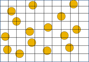
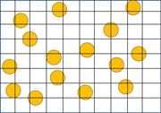
To illustrate the point-counting procedure, Figure 1 shows a 1000X image of a synthetic microstructure consisting of fifteen (15) 17-µm-diameter circular yellow “particles” within a field area of 25,900 µm2 (0.0259 mm2). The total area of the 15 circular particles is 3405 µm2, which is an area fraction of 0.1315 (i.e., 13.15%). This areal measurement is a very accurate estimate of the volume fraction for such a geometrically simple microstructure and will be considered to be the true value. To demonstrate the use of point counting to estimate the volume fraction, a grid pattern was drawn over this field, producing 63 intersection points. Thus, PP is 10/63 or 0.1587 (i.e., 15.87%), which agrees reasonably well with the calculated area fraction (2.72% greater). For a real microstructure, the time required to point count one field is far less than to do an areal analysis on that field. In practice, a number of fields would be point counted and the average value would be a good estimate of the volume fraction in a small fraction of the time required to do areal analysis on an adequate number of fields. An areal fraction measurement can only be done easily when the feature of interest is large in size and of simple shape. Point counting is the simplest and most efficient technique to use to assess the volume fraction. The area fraction, AA, and the point fraction, PP, are unbiased estimates of the volume fraction, VV, as long as the sectioning plane intersects the structural features at random.
The lineal fraction, LL, can also be determined for the synthetic microstructure shown in Figure 1. The length of the horizontal and vertical line segments within the circular particles was measured and found to be 371.9 µm. The total test line length was 2645 µm. Consequently, the lineal fraction is 371.9/2645 or 0.1406 or 14.06 %. This is a slightly higher estimate, about 0.91% greater than obtained by areal analysis. Again, if a number of fields were measured, the average would be a good estimate of the volume fraction. Lineal analysis becomes more tedious as the structural features become smaller. But, for coarse structures, it is rather simple to perform. Lineal analysis is commonly performed when a structural gradient must be measured, that is, a change in second phase concentration as a function of distance from a surface or an interface.
NUMBER PER UNIT AREA
The count of the number of particles within a given measurement area, NA, is a useful microstructural parameter and is used in other calculations. Referring again to Figure 1, there are 15 particles in the measurement area (25900 µm2 or 0.0259 mm2). Hence, the number of particles per unit area, NA, is 0.000579 per µm2 or 579 per mm2. The average cross-sectional area of the particles can be calculated by dividing the volume fraction, VV by NA:
This yields an average area, Ã, of 227.08 µm2, which agrees extremely well with the calculated area of a 17-µm diameter circular particle of 227 µm2. The above example illustrates the calculation of the average area of particles in a two-phase microstructure using stereological field measurements rather than individual particle measurements.
INTERSECTIONS AND INTERCEPTIONS PER UNIT LENGTH, PL and NL
Counting of the number of intersections of a line of known length with particle boundaries or grain boundaries, PL, or the number of interceptions of particles or grains by a line of known length, NL, provides two very useful microstructural parameters. For space-filling grain structures (single phase), PL = NL, while for two-phase structures, PL = 2NL (this may differ by one count in actual cases).
Grain-Structure Measurements
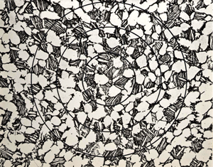
For single-phase grain structures, it is usually easier to count the grain-boundary intersections with a line of known length, especially for circular test lines. This is the basis of the Heyn intercept grain size procedure described in ASTM E 112. For most work, a circular test grid composed of three concentric circles with a total line length of 500 mm is preferred. Grain size is defined by the mean lineal intercept length, l:
This equation must be modified, as described later, for two-phase structures. l can be used to calculate the ASTM grain size number. Grain size determination is discussed below in more detail.
PL measurements can be utilized to define the surface area per unit volume, SV, or the length per unit area, LA, of grain boundaries:
For single-phase structures PL and NL are equal, and either measurement can be used. For two-phase structures, it is best to measure PL to determine the phase-boundary surface area per unit volume, or phase-boundary length per unit area.
Partially Oriented Structures
Many deformation processes, particularly those that are not followed by recrystallization, produce partially oriented microstructures. It is not uncommon to see partially oriented grain structures in metals that have been “cold” deformed. The presence and definition of the orientation (3) can only be detected and defined by examination of specimens on the principle planes. Certain microstructures exhibit a high degree of preferred directionality on the plane of polish or within the sample volume. A structure is completely oriented if all of its elements are parallel. Partially oriented systems are those with features having both random and oriented elements. Once the orientation axis has been defined, then a plane parallel to the orientation axis can be used for measurements. PL measurements are utilized to assess the degree of orientation of lines or surfaces.
|
Table 2. Grain Orientation for Four Specimens of Low-Carbon Sheet Steel
|
 |
|
PL is the number of grain-boundary intersections per miilimeter
|
Several approaches can be utilized to assess the degree of orientation of a microstructure. For single-phase grain structures, a simple procedure is to make PL measurements parallel and perpendicular to the deformation axis on a longitudinally oriented specimen, as the orientation axis is usually the longitudinal direction. The degree of grain elongation is the ratio of perpendicular to parallel PL values — i.e., PL┴ / PL║. Another very useful procedure is to calculate the degree of orientation, Ω, using these PL values:
PL┴ + 0.571 PL
To illustrate these measurements, a section of low-carbon steel sheet was cold rolled to reductions in thickness of 12, 30 and 70%. PL– and PL║ measurements were made using a grid with parallel straight test lines on a longitudinal section from each of four specimens (one specimen for each of the three reductions, plus one specimen of as-received material). The results are given in Table 2. As shown, cold working produces an increased orientation of the grains in the longitudinal direction.
Spacing
The spacing between second-phase particles or constituents has been found to be a very structure sensitive parameter influencing strength, toughness and ductile fracture behavior. NL measurements are more easily utilized in the study of the spacing of two-phase structures than PL measurements. Perhaps the commonest spacing measurement is that of the interlamellar spacing of eutectoid (such as pearlite) or eutectic structures (5). The true interlamellar spacing, σt, is difficult to measure, but the mean random spacing, σr, is readily assessable and is directly related to the mean true spacing:
σt = σr/2 (Eq. 8)
The mean random spacing is determined by placing a test grid consisting of one or more concentric circles on the pearlite lamellae in an unbiased manner. The number of interceptions of the carbide lamellae with the test line(s) is counted and divided by the true length of the test line, to obtain NL. The reciprocal of NL is the mean random spacing:
σr = —— (Eq. 9)
The mean true spacing, σt, is ½ σr. To make accurate measurements, the lamellae must be clearly resolved; hence, use of transmission electron microscope replicas is quite common.
NL measurements are also used to measure the interparticle spacing in a two-phase alloy, such as the spacing between carbides or intermetallic precipitates. The mean center-to-center planar spacing between particles over 360º,σ, is the reciprocal of NL. For the second-phase particles in the idealized two-phase structure shown in Figure 1, a count of the number of particles intercepted by the horizontal and vertical test lines yields 22.5 interceptions. The total line length is 1743 µm; hence, NL = 0.0129 per µm or 12.9 per mm and σ is 77.5 µm or 0.0775 mm.
The mean edge-to-edge distance between such particles over 360º, known as the mean free path, λ, is determined in like manner but requires knowledge of the volume fraction of the particles. The mean free path is calculated from:
λ = ——— (Eq. 10)
For the structure illustrated in Figure 1, the volume fraction of the particles was estimated as 0.147. Hence, λ is 66.1 µm or 0.066 mm.
The mean lineal intercept distance, lα, for these particles is determined by:
lα = σ – λ (Eq. 11)
For this example, lα is 11.4 µm or 0.0114 mm. This value is smaller than the caliper diameter of the particles because the test lines intercept the particles at random, not only at the maximum dimension. The calculated mean lineal intercept length for a circle with a 15-µm diameter is 11.78 µm. Again, stereological field measurements can be used to determine a characteristic dimension of individual features without performing individual particle measurements.
GRAIN SIZE
Perhaps the commonest quantitative microstructural measurement is that of the grain size of metals, alloys and ceramic materials. Numerous procedures have been developed to estimate grain size; these procedures are summarized in detail in ASTM E 112 and described in (6-9). Several types of grain sizes can be measured: ferrite grain size, austenite grain size, and prior-austenite grain size. Each type presents particular problems associated with revealing these boundaries so that an accurate rating can be obtained (6, 9). While this relates specifically to steels, ferrite grain boundaries are identical (geometrically) to grain boundaries in any alloy that does not exhibit annealing twins while austenite grains are identical (geometrically) to grain boundaries in any alloy that exhibits annealing twins. Hence, charts depicting ferrite grains in steel can be used to rate grain size in metals such as aluminum, chromium and titanium while charts depicting austenite grains can be used to rate grain size in metals such as copper, brass, cobalt and nickel.
There are a variety of parameters utilized to measure grain size:
- Average grain diameter, d
- Average grain area, A
- Number of grains per unit area, NA
- Average intercept length, L
- Number of grains intercepted by a line of fixed length, N
- Number of grains per unit volume, NV
- Average grain volume, V
These parameters can be related to the ASTM grain size number, G.
The ASTM grain-size scale was established using the Imperial system of units, but no difficulty is introduced using metric measurements, which is more common. The ASTM grain size equation is:
n = 2G-1 (Eq. 12)
where n is the number of grains per square inch at 100x. Multiplication of n by 15.5 gives the number of grains per square millimetre at 1X, NA. The metric grain size number, GM, which is used by ISO and many other countries, is based upon the number of grains per mm2 at 1X, m, and uses the following formula:
m = 8(2GM) (Eq. 13)
The metric grain size number, GM, is about 4.5% higher than the ASTM grain size number, G, for the same structure, that is:
G = GM – 0.045 (Eq. 14)
This very small difference usually can be ignored (unless the value is near a specification limit).
Planimetric Method
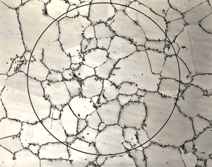
The oldest procedure for measuring the grain size of metals is the planimetric method introduced by Zay Jeffries in 1916 based upon earlier work by Albert Sauveur. A circle of known size (generally 79.8-mm diameter, 5000-mm2 area) is drawn on a photomicrograph or used as a template on a projection screen. The number of grains completely within the circle, n1, and the number of grains intersecting the circle, n2, are counted. For accurate counts, the grains must be marked off as they are counted, which makes this method slow. The number of grains per square millimetre at 1X, NA, is determined by:
NA = f(n1 + n2/2) (Eq. 15)
where f is the magnification squared divided by 5000 (the circle area). The average grain area, A, in square millimetres, is:
and the average grain diameter, d, in millimetres, is:
The ASTM grain size, G, can be found by using the tables in ASTM E112 or by the following equation:
G = [3.322 (log NA – 2.95] (Eq. 18)
Figure 2a illustrates the planimetric method. Expressing grain size in terms of d is being discouraged by ASTM Committee E-4 on Metallography because the calculation implies that grain cross sections are square in shape, which they are not.
In theory, the test line will, on average, bisect grains intercepting a straight line. If the test line is curved, however, bias is introduced (10). This bias decreases as the number of grains within the circle increases. If only a few grains are within the circle, the error is large, e.g., a 10% error if only 10 grains are within the circle. ASTM E 112 recommends adjusting the magnification so that about 50 grains are within the test circle. Under this condition, the error is reduced to about 2% (10). This degree of error is not too excessive. If the magnification is decreased, or the circle is enlarged to encompass more grains, e.g., 100 or more, obtaining an accurate count of the grains inside the test circle becomes very difficult.
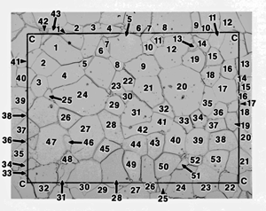
There is a simple alternative to this problem and one that is amenable to image analysis. If the test pattern is a square or rectangle, rather than a circle, bias can be easily eliminated. But, counting of the grains intersecting the test line, n2, is slightly different. In this method, grains will intercept the four corners of the square or rectangle. Statistically, the portions intercepting the four corners would be in parts of four such contiguous test patterns. So, when counting n2, the grains intercepting the four corners are not counted, but a re-weighted as 1. Count all of the other grains intercepting the test square or rectangle (of known size). Equation 15 is modified as follows:
where n1 is still the number of grains completely within the test figure (square or rectangle), n2 is the number of grains intercepting the sides of the square or rectangle, but not the four corners, 1 accounts for the corner grain interceptions and f is the magnification divided by the area of the square or rectangle grid. Figure 2b demonstrates such a counting procedure.
Intercept Method
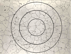
The intercept method, developed by Emil Heyn in 1904, is faster than the planimetric method because the micrograph or template does not require marking to obtain an accurate count. ASTM E 112 recommends use of a template consisting of three concentric circles with a total line length of 500 mm (template available from ASTM). The template is placed over the grain structure without bias, and the number of grain-boundary intersections, P, or the number of grains intercepted, N, is counted. Dividing P or N by the true line length, L, gives PL or NL, which are identical for a single-phase grain structure. It is usually easier to count grain-boundary intersections for single-phase structures. If a grain boundary is tangent to the line, it is counted as ½ of an intersection. If a triple-point line junction is intersected it is counted as 1½ or 2. The latter is preferred because the small diameter of the inner circle introduces a slight bias to the measurement that is offset by weighing a triple-line intersection as 2 hits.
The mean lineal intercept length, l, determined as shown in Eq 4, is a measure of ASTM grain size. l is smaller than the maximum grain diameter because the test lines do not intersect each grain at their maximum breath. The ASTM grain size, G, can be determined by use of the tables in ASTM E112 or can be calculated from:
G = [-6.644 (log l) – 3.288] (Eq. 19)
where l is in millimetres. Figure 3 illustrates the intercept method for a single-phase alloy.
Nonequiaxed Grains
Nonequiaxed grain structures require measurements on the three principle planes i.e., the longitudinal, planar and transverse planes (in practice, measurements on any two of the three are adequate). For such structures, the intercept method is preferred, but the test grid should consist of a number of straight, parallel test lines of known length, rather than circles, oriented as described below. Because the ends of the straight lines generally end within grains, these interceptions are counted as half-hits. Three mutually perpendicular orientations are evaluated using grain-interception counts:
- NL1 – parallel to the grain elongation, longitudinal or planar surface
- NL1 – perpendicular to the grain elongation (through-thickness direction), longitudinal or transverse surface
- NLP – perpendicular to the grain elongation (across width), planar or transverse surface.
The average NL value is obtained from the cube root of the product of the three directional NL values. G is determined by reference to the tables in ASTM E 112 or by use of Eq. 19 (l is the reciprocal of NL, Eq. 4).
Two-Phase Grain Structures
The grain size of a particular phase in a two-phase structure requires determination of the volume fraction of the phase of interest – e.g., by point counting. The minor phase (second phase) is point-counted and the volume fraction of the major phase (matrix phase) is determined by difference.
Next, a circular test grid is applied to the microstructure without bias and the number of grains of the phase of interest intercepted by the test line, Nα , is counted. The mean lineal intercept length of the alpha grains, lα is determined by:
where L is the line length and M is the magnification. The ASTM grain size number can be determined from the tables in ASTM E 112 or by use of Eq. 19. The method is illustrated in Figure 4. Again, a circular test grid will introduce some bias in counting (as described before for the planimetric method), if the number of interceptions is low. This can be eliminated by using a square or rectangular test grid and counting as described above (the grains intercepted by the four corners are counted as 1, while all of the grains intercepting the sides are weighted as one each.
INCLUSION CONTENT
Assessment of inclusion types and contents is commonly performed on high-quality steels. Production evaluations utilize comparison chart methods such as those described in ASTM E 45, SAE J422a, ISO 4967, or the German standard SEP 1570 (DIN 50602). In these chart methods, the inclusion pictures are defined by type and graded by severity (amount). Either qualitative procedures (worst rating of each type observed) or quantitative procedures (all fields in a given area rated) are employed. Only the Japanese standard JIS-G-0555 uses actual volume fraction measurements for the rating of inclusion content (although the statistical significance of the data is questionable due to the limited number of counts required).
Manual measurement of the volume fraction of inclusions requires substantial effort to obtain acceptable measurement accuracy due to the rather low volume fractions usually encountered (11). When the volume fraction is below 0.02 (2%), which is the case for inclusions, even in free machining steels, acceptable relative accuracies (see Eq. 22) cannot be obtained by manual point counting without a vast amount of counting time (11). Consequently, extensive use of image analyzers has been made to overcome this problem. Image analyzers separate the oxide and sulfide inclusions on the basis of their gray-level differences. By using automated stage movement and autofocusing, enough field measurements can be made in a relatively short time to obtain reasonable statistical precision. Image analysis is also employed to measure the length of inclusions and to determine stringer lengths.
Two image analysis based standards have been developed, ASTM E 1122 (12) and E 1245 (13-16). E 1122 produces JK ratings by image analysis that overcome most of the weaknesses of manual JK ratings. E 1245 is a stereological approach defining, for oxides and sulfides, the volume fraction (VV), number per unit area (NA), average length, average area and the mean free path (spacing in the through-thickness direction). These data are easily data based and are statistical in that means and standard deviations are developed so that data from different tests can be compared using statistical methods to determine if the differences between the measurements are valid at a particular confidence level.
MEASUREMENT STATISTICS
In performing stereological measurements, it is necessary to make these measurements on a number of fields and average the results. Measurements on a single field may not be representative of the bulk conditions, because few (if any) materials are sufficiently homogeneous. Calculation of the standard deviation of the field measurements gives a good indication of measurement variability. Calculation of the standard deviation can be done quite simply with an inexpensive pocket calculator.
A further refinement of statistical analysis is calculation of the 95% confidence limit based on the standard deviation, s, of the field measurements. The 95% confidence limit is calculated from:
where t is the Student’s t value that varies with N, the number of measurements. Many users standardize on a single value of t, 2, for calculations irrespective of N. The measurement value is expressed as the average, X, ± the 95% CL value. This means that if the test were conducted 100 times, the average values would be between plus and minus the average, X, in 95 of the measurements. Next, one can calculate the relative accuracy, % RA, of the measurement by:
Usually, a 10% relative accuracy is considered to be adequate. DeHoff (17) has developed a simple formula to determine how many fields, N, must be measured to obtain a specific desired degree of relative accuracy at the 95% confidence limit:
IMAGE ANALYSIS
The measurements described in this brief review, and other measurements not discussed, can be made by use of automatic image analyzers. These devices rely primarily on the gray level of the image on the television monitor to detect the desired features. In some instances, complex image editing can be utilized to aid separation. Some structures, however, cannot be separated completely, and for these structures the semiautomatic digital tracing devices can be utilized to improve measurement speed.
SUMMARY
This chapter has reviewed many of the simple stereological counting measurements and simple relationships based on these parameters. More complex measurements are discussed at length elsewhere in this text. The measurements described are easy to learn and use. Their application enables the metallographer to discuss microstructures in a more quantitative manner and reveals relationships between the structure and properties of the material.
References
- G. A. Moore, “Is Quantitative Metallography Quantitative?,” Application of Modern Metallographic Techniques, STP 480, American Society for Testing and Materials, Philadelphia, PA, 1970, pp. 3-48.
- E. E. Underwood, “Applications of Quantitative Metallography,” Metals Handbook, 8th Ed., Vol. 8, American Society for Metals, Metals Park, OH, 1973, pp. 37-47.
- E. E. Underwood, Quantitative Stereology, Addison-Wesley, Reading, MA 1970.
- J. E. Hilliard and J. W. Cahn, “An Evaluation of Procedures in Quantitative Metallography for Volume-Fraction Analysis,” Trans. AIME, Vol. 221, April 1961, pp. 344-352.
- G. F. Vander Voort and A. Roósz, “Measurement of the Interlamellar Spacing of Pearlite,” Metallography, Vol.. 17, Feb. 1984, pp. 1-17.
- H. Abrams, “Grain Size Measurements by the Intercept Method,” Metallography, Vol. 4, 1971, pp. 59-78.
- G. F. Vander Voort, “Grain Size Measurement,” Practical Applications of Quantitative Metallography, STP 839, American Society for Testing and Materials, Philadelphia, 1984, pp. 85-131.
- G. F. Vander Voort, “Examination of Some Grain Size Measurement Problems,” Metallography: Past, Present and Future, STP 1165, American Society for Testing and Materials, Philadelphia, 1993, pp. 266-294.
- G. F. Vander Voort, Metallography: Principles and Practice, ASM International, Materials Park, OH, 1999.
- S.A. Saltykov, Stereometric Metallography, 2nd ed., Metallurgizdat, Moscow, 1958.
- G. F. Vander Voort, “Inclusion Measurement,” Metallography as a Quality Control Tool, Plenum Press, New York, 1980, pp. 1-88.
- G. F. Vander Voort and J. F. Golden, “Automating the JK Inclusion Analysis,” Microstructural Science, Vol. 10, Elsevier North-Holland, NY, 1982, pp. 277-290.
- G. F. Vander Voort, “Measurement of Extremely Low Inclusion Contents by Image Analysis, Effect of Steel Manufacturing Processes on the Quality of Bearing Steels, STP 987, American Society for Testing and Materials, Philadelphia, PA, 1988, pp. 226-249.
- G. F. Vander Voort, “Characterization of Inclusions in a Laboratory Heat of AISI 303 Stainless Steel,” Inclusions and Their Influence on Materials Behavior, ASM International, Metals Park, OH, 1988, pp. 49-64.
- G.F. Vander Voort, “Computer-Aided Microstructural Analysis of Specialty Steels,” Materials Characterization, Vol. 27, No. 4, December 1991, pp. 241-260.
- G. F. Vander Voort, “Inclusion Ratings: Past, Present and Future,” Bearing Steels Into the 21st Century, STP 1327, American Society for Testing and Materials, West Conshohocken, PA, 1998, pp. 13-26.
- R. T. De Hoff, “Quantitative Metallography,” Techniques of Metals Research, Vol. II, Part 1, Interscience, New York, 1968, pp. 221-253.
George Vander Voorthas a background in physical, process and mechanical metallurgy and has been performing metallographic studies for 43 years. He is a long-time member of ASTM Committee E-4 on metallography and has published extensively in metallography and failure analysis. He regularly teaches MEI courses for ASM International and is now doing webinars. He is a consultant for Struers Inc. and will be teaching courses soon for them. He can be reached at 1-847-623-7648, EMAIL: georgevandervoort (AT) yahoo (DOT) com and through his web site: www.georgevandervoort.com
To View a listing of all George’s articles please click here
Read George Vander Voort’s Biography

