Abstract
 After we have properly prepared our tool steel specimens, it is generally best to examine them as-polished before etching – unless we are simply doing a routine test, for depth of decarburization, degree of spheroidization, and so forth. Examination of selectively etched tool steel microstructures by light microscopy provides more information than standard etchants, such as nital, picral or Vilella’s reagent. Further, the images are more suitable for quantitative measurements, especially by image analysis. Specimens must be properly prepared, damage free, if selective etchants, or color etchants, are to be applied successfully.
A number of etchants have been claimed to selectively etch certain carbides in tool steels. The response of these etchants has been evaluated using a variety of well-characterized tool steel compositions. While many are selective, they are often selective to more than one type of carbide. Furthermore, their use in image analysis must be evaluated carefully as measurements showed that the amount and size of the carbides are often greater after selective etching as many of these reagents outline and color or attack the carbides. Selective etching of the matrix, leaving the carbides unaffected, works well, but no one etchant will cover the broad spectrum of tool steel compositions. No etchant has been found that will color retained austenite in tool steels (unless the amount is quite high) and image analysis results for retained austenite in tool steels are always much lower than determined by x-ray diffraction unless retained austenite is the dominant phase present in grossly over-austenitized steels. In general, we cannot see the retained austenite in a tool steel until the amount is above ~12-15%.
THE LIGHT OPTICAL MICROSCOPE
 |
|
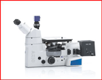
Figure 1. The Zeiss Axio Vert A1 MAT inverted reflected light microscope.
|
It will not help much if you have perfectly prepared specimens, etched with the best reagents, if you do not have a reflected light microscope of acceptable quality (with a good CCD camera and software). This instrument is the heart and soul of the lab. Reflected light microscopes come in either upright or inverted formats. Each has advantages and disadvantages. With an upright microscope you do need to level your specimen on a slide using clay so that the polished surface is perpendicular to the optical axis. But, we can see the entire specimen surface and we know exactly where the beam is located on the specimen. With an inverted microscope, we do not need to level the specimen, but not all of the specimen may be available to be observed and it is hard to determine exactly where the light beam is on the specimen. Figure 1 shows the Zeiss Axio Ver A1 MAT inverted light microscope which has all of the imaging modes and excellent optical quality.
The vast majority of microstructural observations are done with bright field illumination. Generally that is adequate, but it is not always the best. If we color etch, and the coloring is a little weak, we can vastly improve the image quality by using cross polarized light with a sensitive tint filter (sometimes called a first-order red plate or a lambda plate). Viewing the image slightly off the crossed position may be helpful. Also, an adjustable sensitive tint filter is useful in setting the color to its best position. Dark field (sometimes called dark ground) imaging gives the reverse contrast to bright field. In bright field, any feature perpendicular to the light bean is bright while height affects or crevices scatter light and appear to be dark. In dark field, the scattered light is collected while the light from features perpendicular to the beam is blocked. So, flat areas look black and crevices, etc., look bright and “self-luminous.” Resolution is actually somewhat better in dark field than in bright field. Nomarski differential interference contrast (DIC) is a very useful mode for revealing height variations on the specimen’s surface that are invisible in bright field. This is useful when we have specimens with substantial residual carbides. But, to use these other imaging modes effectively, we need to try them.
ETCHING
The etchant most widely used for tool steels is nital. Etchants useful with tool steels are listed in Table 1. Concentrations from 2 to 10% have been used. Generally, 2 or 3% nital is adequate for most tool steels while a 10% concentration is required for highly alloyed tool steels, such as the D types. Stock solutions exceeding 3% HNO3 in ethanol should not be stored in pressure-tight bottles. If higher concentrations are desired as a stock reagent, a bottle with a pressure-relief valve should be used, or methanol should be substituted for ethanol. Methanol is a cumulative poison and its use should be minimized.
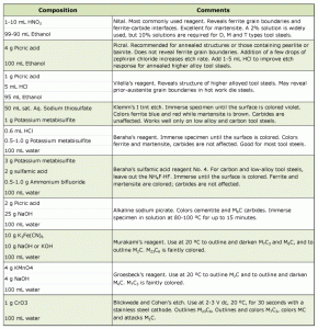
Nital is generally used for tool steels regardless of the anticipated microstructural constituents. Although nital is superior to picral (4% picric acid in ethanol) for etching martensitic structures, picral produces better results for examining annealed samples.
When examining spheroidize-annealed tool steels (the most common annealed condition), picral reveals only the interfaces between carbide and ferrite. Nital also reveals the ferrite grain boundaries that generally obscure the carbide shape. Also, because nital is orientation sensitive, carbides within some of the ferrite grains will be poorly delineated, making spheroidization ratings more difficult.
A 2% nital solution is usually preferred. Stronger concentrations increase the speed of etching, making it more difficult to control. Etching of martensitic high-alloy tool steels, such as the high-speed steels, may require a 5% concentration, while the D types may require a 10% solution. Etching with nital or picral is usually performed by immersion. If swabbing is used, pressures should be light to avoid smearing problems. Etching times are difficult to generalize, because of the wide range of tool steel compositions and because heat treatment can markedly alter etch response. Trial and error will determine the degree of surface dulling necessary to obtain the correct degree of etching. Other etchants, although infrequently used, can be of greater value. Table 1 lists compositions of a number of specialized reagents for achieving selective etching or enhancing contrast among microconstituents.
MICROSTRUCTURE EXAMPLES
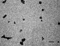
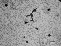
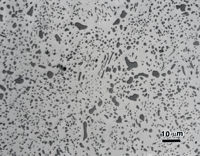
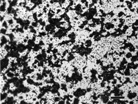
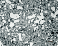
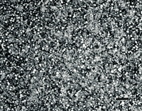
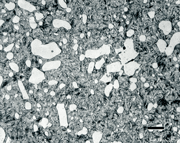
Figure 2 illustrates the use of the three- and four-step preparation methods with annealed O6 graphitic tool steel as an example. Note that the graphite has been fully retained regardless of the method used, and that there is no residual deformation or scratches in the ferrite and the cementite is clearly revealed.
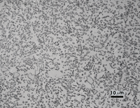
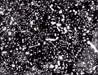
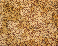
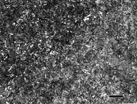
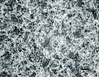
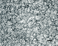
Figure 3 shows the etched microstructure of spheroidize annealed W1 water hardening tool steel etched with 4% picral, with Klemm’s I reagent, and with alkaline sodium picrate. Picral uniformly dissolves the ferrite, thus appearing to outline the cementite particles. Klemm’s I colors the ferrite matrix, but not the cementite, permitting easy discrimination of the cementite by image analysis. Alkaline sodium picrate colors the cementite uniformly, and does not attack or enlarge the particles. Hence, measurements of the cementite will be statistically equivalent using Klemm’s or alkaline sodium picrate.
Figure 4 shows a 0.75-inch diameter bar of W1 water-hardening carbon (1.05%) tool steel after brine quenching (not tempered). The martensitic case structure is revealed (a) using 2% nital, but is not revealed (b) using 4% picral. Picral will reveal tempered martensite, but not as-quenched (unless you introduce a fair amount of heat in sectioning and preparation). The case contains some undissolved cementite because the proper austenitizing temperature is chosen to dissolve only about 0.6% C of the total 1.05% C. If the austenitizing temperature is raised high enough to dissolve all of the 1.05% C, then the Ms and Mf temperatures will be depressed so that only part of the austenite is transformed to martensite – it will be coarse plate martensite and retained austenite (which is very bad for die life). Image (c) shows the transition where the case ends and the core begins. Etching with 4% picral is much better for seeing this change as the as-quenched martensite stays white while the fine pearlite is dark; the high contrast makes it easy to see the 50:50 transition point. The core microstructure (d) is unresolvable pearlite, which is better revealed with picral than nital (nital is orientation sensitive and some pearlite colonies will be lightly etched).
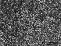
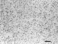
Figure 5 shows examples of typical tempered martensitic microstructures of four tool steels: type L6 (compositionally, 4370 alloy steel), H13 hot work die steel, D3 cold work die steel; and T15 high speed steel (made by powder metallurgy to obtain a uniform distribution of fine alloy carbides).

Experiments with a number of tool grades in either the annealed or quenched and tempered condition, or both, were conducted to assess the selectivity of the etchants listed in Table 1 that are claimed to outline, color, outline and color, or attack specific carbide types. The carbides were first characterized by electron-backscattered diffraction (EBSD). Before each etching was used the specimens were completely re-prepared. Results are given in Table 2.
CONCLUSIONS
Specimen preparation must be properly performed if the true structure is to be observed and interpreted correctly. With modern semi-automated equipment, tool steel specimens can be prepared quickly and with perfect results every time. Simple three- and four-step procedures have been described. Key factors in preparing specimens were defined. First, sectioning of the specimen requires an abrasive blade designed for metallographic work and for the hardness of the particular specimen to avoid introducing excessive damage. Second, if an edge is to be examined, mount the specimen in the best possible resin. Third, commence grinding with the finest possible abrasive. Fourth, used enough abrasive in polishing to produce effective cutting. Fifth, use napless, woven or pressed cloths, except in the final step. Finally, select the best etchant to reveal the structure clearly and with good contrast.
George Vander Voort has a background in physical, process and mechanical metallurgy and has been performing metallographic studies for 43 years. He is a long-time member of ASTM Committee E-4 on metallography and has published extensively in metallography and failure analysis. He regularly teaches MEI courses for ASM International and is now doing webinars. He is a consultant for Struers Inc. and will be teaching courses soon for them. He can be reached at 1-847-623-7648, EMAIL: georgevandervoort (AT) yahoo (DOT) com and through his web site: www.georgevandervoort.com
To View a listing of all George’s articles please click here
Read George Vander Voort’s Biography

