Welding is a very important joining process and has been used extensively for at least the past 75 years. There is a need to control processes, such as welding, to ensure a high-quality end result. Over the years there have been many spectacular failures of welded structures, starting with Liberty ship and T-2 tanker failures during WWII, that emphasize this need. Many procedures involving non-destructive and destructive tests are used to study weldments. A metallographic examination can be performed in-situ by grinding an area on the surface of the weld, its heat affected zones and adjacent base metal (the metal being joined that was unaffected by the temperature of the welding process). This is a reasonably non-destructive evaluation. Destructive examination, where a specimen is removed from either the welded assembly or test coupons, is quite commonly performed. Test coupons are often used to qualify the welder and ensure that the techniques and materials chosen will produce a weld with acceptable soundness and mechanical properties. Post mortems of failed weldments are also examined metallographically using sections removed from the welded assembly, generally after the non-destructive examination is completed.
Welded structures can be quite large and, in the case of a field failure, flame-cutting may be the only way to remove a section for study. This process produces a substantially damaged zone adjacent to the cut, often as wide as 10 – 15 mm. When the section gets to the laboratory, the region damaged by flame cutting must be removed by a much less-damaging cutting method, such as band sawing or abrasive sectioning. Then, the metallographer should cut out coupons using a laboratory abrasive cut-off saw that introduces less damage than production machine shop equipment. Weld samples often tend to be large and irregular in shape. Many will not fit within a standard 1-, 1.25-, 1.5- or 2-inch (25-, 30-, 40- or 50-mm) diameter mold for hot compression molding. In such cases, the metallographer must use large silicone rubber molds, or build a mold using bent sheet metal, coated perhaps with a mold release agent, and glued to a base plate. Then, the specimen is placed inside the mold and is encapsulated with epoxy resin. After it has cured, the specimen can be ground and polished using a wide variety of semi-automated equipment.
The specimen is examined in the as-polished condition for voids of different types, such as porosity from gas evolution or shrinkage cavities, cracks that may be present in either the weld metal or the heat-affected zone, regions where the weld metal did not penetrate (lack of fusion or lack of penetration) and for nonmetallic inclusions associated with the welding operation, chiefly slag-type in nature. Then, the metallographer will etch the specimen to study both the macrostructure and the microstructure using an etchant appropriate for the alloy. In some cases, the weld metal is of sufficiently different composition that an etchant is chosen to etch the base metal and heat affected zone will not properly reveal the weld metal structure and vice versa. If the specimen has been polished, the macrostructural details are usually adequately revealed by the etchant used to reveal the microstructure. In some studies, the metallographer will macroetch the specimen after grinding and study the macrostructure. This specimen is not suitable for microstructural examination until it is polished.

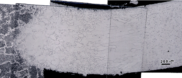
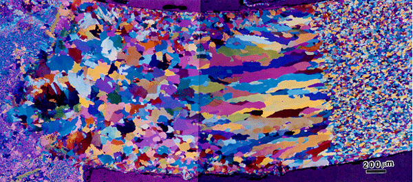
Most etchants used to reveal the structure of welds are standard general-purpose etchants. After examination with such an etch, it may prove to be valuable to use a color etching technique, as these can be far more sensitive for revealing grain structure, segregation, and residual strain and deformation. However, these etchants are not widely used. Their use does require a very well prepared specimen for good results. But this level of perfection is easily achieved with modern equipment and consumable products. Figure 1 shows an example of the superiority of color etching over standard etchants in revealing the grain structure of a low-carbon steel weld.
Figure 1. is an example of a welded low-carbon steel etched with 2% nital and figure 2., is an example of Klemm’s I showing the clear superiority of color etching in revealing the grain structure. The as-cast weld metal is shown at the far left and the base metal is shown at the far right, above the µm bar. In between, we see the heat-affected zone starting with coarse irregular grains adjacent to the fusion line, progressing to finer more uniformly shaped grains, then to columnar grains and finally to the very fine-grained equiaxed ferrite grains in the base metal.

George Vander Voort has a background in physical, process and mechanical metallurgy and has been performing metallographic studies for 45 years. He is a long-time member of ASTM Committee E-4 on metallography and has published extensively in metallography and failure analysis. He regularly teaches MEI courses for ASM International and is now doing webinars. He is a consultant for Struers Inc. and will be teaching courses soon for them. He can be reached at 1-847-623-7648, EMAIL: georgevandervoort@yahoo.com and through his web site: www.georgevandervoort.com
To view a listing of all George’s articles please click here
Read George Vander Voort’s Biography
