Relatively few metallographers work with precious metals, other than those used in electronic devices. Precious metals are very soft and ductile, deform and smear easily, and are quite challenging to prepare. Pure gold is very soft and the most malleable metal known. Alloys, which are more commonly encountered, are harder and somewhat easier to prepare. Gold is difficult to etch. Silver is very soft and ductile and prone to surface damage from deformation. Embedding of abrasives is a common problem with both gold and silver and their alloys. Iridium is much harder and more easily prepared. Osmium is rarely encountered in its pure form; even its alloys are infrequent subjects for metallographers. Damaged surface layers are easily produced and grinding and polishing rates are low. It is quite difficult to prepare. Palladium is malleable and not as difficult to prepare as most of the precious metals. Platinum is soft and malleable. Its alloys are more commonly encountered. Abrasive embedment is a problem with Pt and its alloys. Rhodium is a hard metal and is relatively easy to prepare. Rh is sensitive to surface damage in sectioning and grinding. Ruthenium is a hard, brittle metal that is not too difficult to prepare.
PREPARATION METHODS
A procedure for an automated system was developed after experimentation with a number of precious metal specimens. Most of these metals and alloys are quite soft, unless they have been cold worked, and they are susceptible to the embedding of abrasives. In this method, only one silicon carbide step is used. DP-Pan cloths are used for the diamond steps, as it will hold the abrasive in its surface well, which minimizes embedding. Only diamond paste is used, as slurries will be more prone to embedding, as we observed in high gold alloys. Use only a small amount of distilled water as the lubricant. Do not get the cloth too wet. Final polishing is with an OP-Chem cloth and OP-AN alumina. Due to their excellent corrosion resistance, colloidal silica is not as effective as an abrasive for precious metals. The OP-Chem cloth has lots of fine pores to hold the abrasive. The procedure is given in Table 1.
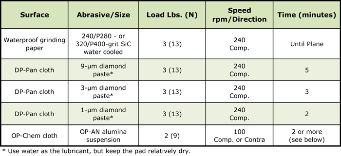
For 18-karat gold and higher (≥75% Au), it is necessary to use an attack polish agent in the final step. An aqueous solution of 5g CrO3 in 100 mL water works well. Mix 10 mL of the attack polish agent with 50 mL of the OP-AN suspension. This will thicken, so add about 20-30 mL water to make it thinner. A 3 to 6-minute attack polish step will remove the fine polishing scratches. But, wear protective gloves, as the chromium trioxide solution is a strong oxidizer.
ETCHANTS
Precious metals are quite difficult to etch because of their extremely good corrosion resistance. Most have face-centered cubic crystal structures, except for osmium and ruthenium which are hexagonal close-packed and will respond to polarized light. Otherwise, etchants must be used. Etchants used to prepare the illustrations in this paper, and others not shown, are listed in Table 2 (1).
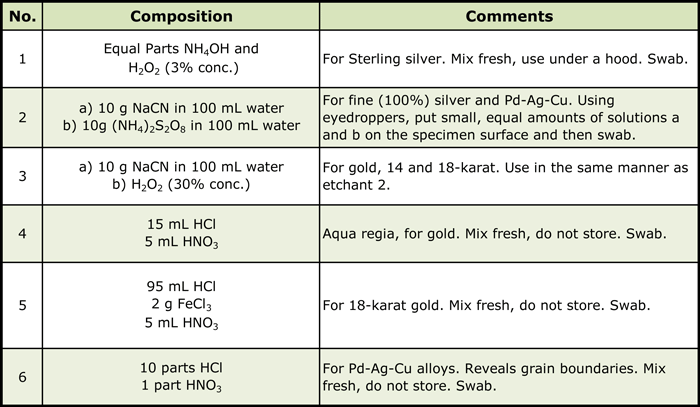
These are all strong etchants and are dangerous to use. Use under a hood with care. Proper protective safety equipment should be used, as well as good laboratory practices. Clean up any spills immediately.
MICROSTRUCTURES
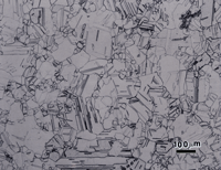
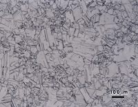
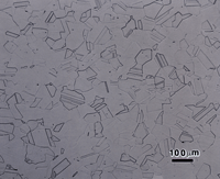
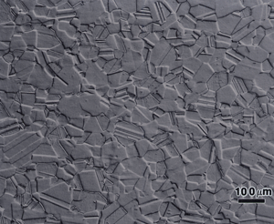
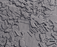
The microstructures of wrought Sterling silver (min. of 92.5% Ag) and fine silver (100% Ag) are shown in Figures 1 and 2 after etching, respectively, with reagents 1 and 2. Silver is face-centered cubic and wrought alloys exhibit annealing twins, much like copper. In such twinned fcc metals, it is difficult to bring up all of the grain and twin boundaries, and silver is no exception. But, in both micrographs, a high percentage of the boundaries are revealed. The etching was stopped when a slight degree of over-etching started. Both specimens seem to exhibit duplex grain size distributions.
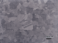
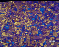
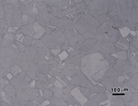
Figure 3 shows the microstructure of wrought 14-karat gold (58% Au) after a first etch with reagent 3. The surface exhibited a slight grain contrast etch, which responded to cross-polarized light, Figure 4, producing colors (yellow-blue-violet).
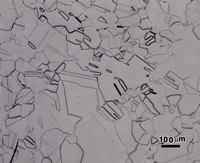
The polarized light response was due to the slight roughening of the surface by the etchant and is not the desired results. Figure 5 shows the same specimen after re-polishing (repeating step 5, but with the attack, polishing agent added) and re-etching with reagent 3. Now we observe the correct “flat” etch response. Again, some of the grain and twin boundaries are not visible or are faintly visible. Longer etching times would bring out more of the boundaries but would result in some being over-etched. If this specimen is examined with Nomarski differential interference contrast illumination, as in Figure 6, more of the grain structure can be observed. DIC will reveal any damage to the microstructure that was not removed by the preparation method. Figure 6 reveals almost no damage at all.
Figure 7 shows the microstructure of 18-karat gold, Neyoro 28A (75% Au-22% Ag-3% Ni) in the annealed condition (about 45 HV) etched with reagent 4, aqua regia. While the grain structure is visible, the contrast is quite low. Etchant 3 produced much better results as shown in Figure 8. Some boundaries are slightly over-etched and a few are not visible or are faint, but the grain size can be evaluated. Again, if Nomarski DIC is used, Figure 9, the results are better. This shows a very slight amount of scratches remaining in some of the grains, but they are too faint to be seen in bright field illumination (Fig. 8).
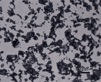
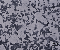
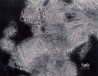
Figures 10 and 11 show the microstructure of solution annealed and aged Paliney 8 (44% Pd-38% Ag-1% Ni-16% Cu) with a hardness of about 335 HV. Figure 10 shows it after etching with reagent 2 and Figure 11 shows it after etching with reagent 6. Both etchants revealed a second phase constituent that looks much like pearlite in steels. Etchant 2 revealed this constituent with greater contrast than etchant 6. However, etchant 6 revealed the grain boundaries in the Pd-Ag-Ni rich matrix. So, the results were much like the difference between etching carbon steel with picral vs. nital. Higher magnification examination with the scanning electron microscope, Figure 12, confirmed the constituent is a lamellar two-phase mixture, possibly of the matrix phase and ß phase, CuPd, but it was not identified.
CONCLUSIONS
This work demonstrated that automated polishing procedures can be used to prepare precious metal specimens and that the damage due to sectioning and grinding can be removed. The procedure is unconventional but straightforward. Etchants for precious metals are very strong, dangerous solutions. But, with proper laboratory procedures and precautions, they can be safely used.
REFERENCES
1. G.F. Vander Voort, Metallography: Principles and Practice, McGraw-Hill, NY, 1984, ASM International, Materials Park, OH, 1999.
George Vander Voort has a background in physical, process and mechanical metallurgy and has been performing metallographic studies for 45 years. He is a long-time member of ASTM Committee E-4 on metallography and has published extensively in metallography and failure analysis. He regularly teaches MEI courses for ASM International and is now doing webinars. He is a consultant for Struers Inc. and will be teaching courses soon for them. He can be reached at 1-847-623-7648, EMAIL: georgevandervoort@yahoo.com and through his web site: www.georgevandervoort.com
To View a listing of all George’s articles please click here
Read George Vander Voort’s Biography

