
Grain size is probably the most frequent microstructural measurement due to its influence on properties and behavior/service performance. Grain size can be determined by several methods. Chart comparison ratings are probably the most often performed, as this method is fast and simple. But its accuracy is at best ± 1 G value. An ASTM E-4 interlaboratory round robin test using Plate I of ASTM E 112 showed that chart ratings were biased with the rating being ½ to 1 G value coarser than the actual measured grain size. Similar studies have not been conducted with Plates II or III. Actual measurements of grain size are done by either the planimetric or the intercept methods, as defined in E 112. These are unbiased methods, as long as the grain boundaries were properly delineated by the etchant. Experience has shown that measuring the grain size of BCC metals is much easier than measuring the grain size of FCC metals and alloys that contain annealing twins. ASTM E 112 has two comparison charts for such metals; Plate II for specimens that exhibit a so-called “flat” etch appearance and Plate III for those that exhibit a grain contrast etchant response. Plate III was developed using copper specimens and the images are at 75X, while the other E 112 charts are at 100X. To further confuse the issue, Plate III expresses grain size in terms of d, the average grain diameter, calculated by taking the square root of the average grain area (which is the reciprocal of the number of grains per mm2), rather than as an ASTM grain size number, G.
Proper delineation of the grain boundaries is of utmost importance when making measurements. This is not a trivial issue; it is challenging. For austenitic stainless steels and some Ni-based alloys, there are a few etchants that will reveal the grain boundaries quite well without revealing the annealing twins – the ideal condition. But, such etchants do not exist for Cu and Cu-based alloys, or for Ag and Au.
In this study, a variety of austenitic stainless steel specimens were cold worked and then solution annealed at various temperatures to vary the grain size. The austenitic stainless steel specimens were first etched with aqueous 60% HNO3 at 1.5 V dc, for 60-120 s [1] to delineate only the grain boundaries, Fig. 1. After counting the number of grain boundary intersections with test lines to obtain PL, the specimens were re-prepared and etched with standard reagents that reveal both grain and twin boundaries. The number of grain and twin boundary intersections per unit length, PL’ was determined for each specimen. Results were plotted and least-square regression equations were calculated to determine how well the true ASTM grain size number can be determined from PL’, rather than PL.
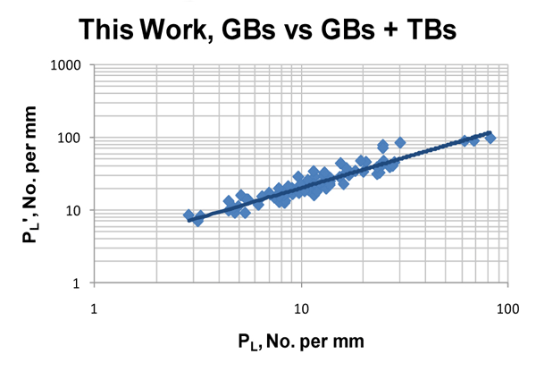
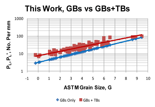
Figure 2 shows the relationship between PLand PL’, that is between the number of grain boundary intersections per mm and the number of grain and twin boundary intersections per mm. There is a good consistent correlation. Three data points are for a Ni-base alloy. Figure 3 shows the correlation between the ASTM grain size, G, and PLand PL’. The three data points for the Ni-based alloy do not correlate very well with the measurements for the 7 different austenitic stainless steels. The data correlates well with previous published data for 316 and 316L stainless steel and for cartridge brass.
 |
 |
|
Figure 1. AISI 316L austenitic stainless steel solution annealed at 1750°F and etched with (left) Kallings No. 2 and (right) aqueous 60% HNO3 at 1.5 V dc for 120 s (scale bars are both 50µm in length).
|
|
 |
 |
|
Figure 2 (left). Correlation between PL (grain boundaries only) and PL’ (grain boundaries and twin boundaries) reveals that PL’ is > PL, as expected. Figure 3 (right). Correlation between the ASTM grain size, G, and P or PL’ reveals that the true grain size, G, can be predicted from PL’ when both grain and twin boundary intersections are counted.
|
|
References
[1]. F.C. Bell and D.E. Sonon, Metallography, Vol. 9, 1976, pp. 91-107.George Vander Voort has a background in physical, process and mechanical metallurgy and has been performing metallographic studies for 45 years. He is a long-time member of ASTM Committee E-4 on metallography and has published extensively in metallography and failure analysis. He regularly teaches MEI courses for ASM International and is now doing webinars. He is a consultant for Struers Inc. and will be teaching courses soon for them. He can be reached at 1-847-623-7648, EMAIL: georgevandervoort@yahoo.com and through his web site: www.georgevandervoort.com
To View a listing of all George’s articles please click here
Read George Vander Voort’s Biography