Abstract
When ASTM standard E 2 was published in 1917, ASTM Committee E-4 on Metallography’s first standard, it described the planimetric method for measuring grain size based upon publications by Zay Jeffries, a founding member of E-4. Jeffries was a graduate student under the famous Harvard professor, Albert Sauveur. Sauveur published a paper in 1894 where he defined grain structures in terms of the number of grains per square mm at 1X. But, he did not develop details on his method. This method is more tedious to use than the Heyn intercept method because a count of the grains must be made by physically marking the grains as they are counted, when done manually. Experiments were conducted to determine the influence of the number of grains counted per grid application using the Jeffries planimetric procedure of ASTM E 112 with a single test circle of varying size. Results show that this is a viable test method and produced good data down to relatively low count numbers per grid application. Bias was not observed at low counts, only data scatter.
The Planimetric Method
ASTM Committee E-4 on Metallography was founded in 1916. Their first standard, ASTM E 2 was proposed in 1917 [1], it included a detailed description of how to measure grain size using the planimetric method written by Zay Jeffries [2,3], based upon earlier work done by his graduate school advisor, Albert Sauveur [4]. Sauveur was the first to measure grain size and he defined it in terms of the number of grains per mm2 at 1X; but, he did not describe how he made the measurement. The ASTM equation relating the number of grains per in2 at 100X and the ASTM grain size number was introduced in 1951 by an undocumented Timken member of E-4 when E 91-51T was introduced [5]. The equation is:
n = 2G-1 (1)
where n is the number of grains per in2 at 100X and G is the ASTM grain size number.
The Jeffries planimetric grain size method utilized a test circle with a diameter of 79.8 mm which was superimposed over the microstructure. The magnification was chosen to give at least 100 grains to be counted (this number was later reduced to ~50 when a round robin test program showed that counting errors were higher when ~100 grains were counted per grid application). The wording, as written, could be interpreted two ways and could be improved. It would be better to say that ~50 grains should be inside and intersecting the test circle. The rater must count all the grains that are completely inside the test circle, ninside, and all the grains that are intercepted by the circle, nintercepted. It is assumed that, on average, half of the intercepted grains are inside the test circle and half are outside. To get an accurate count, the operator must mark off the grains as they are counted using a felt tip pen, etc. This, however, makes the method slow and less popular. But, this is not a problem if image analysis is used. The calculation is:
NA = f(ninside + 0.5nintercepted) (2)
where NA is the number of grains per mm2 at 1X and f is the Jeffries multiplier:
f = M2/A (3)
and M is the magnification and a is the area (5000 mm2 is the standard size). If the test area is different than 5000 mm2 (from a circle 79.8 mm diameter), then the alternate area used is divided into the magnification squared.
The average grain area, A, is the reciprocal of NA. The ASTM grain size number is calculated by:
G = 3.321928 LogNA – 2.954 (4)
G is rounded off to the nearest tenth value. In practice, more than one field must be evaluated to obtain a good estimate of G.
Experimental Program
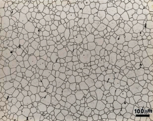
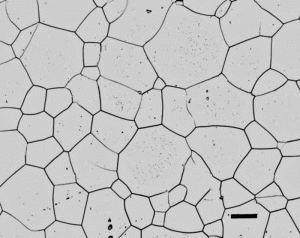
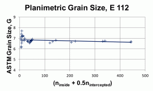
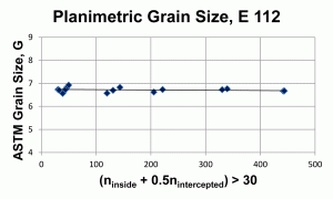
The purpose of the experimental work reported here is to determine how the number of counts inside the test figure affects the calculated grain size, G, and to determine if bias occurs with low counts, as suggested by Saltykov [6]. Two images of a ferritic stainless steel, Figure 1, etched electrolytically with aqueous 60% nitric acid, were used for the experiments. The magnifications were 100 and 400X and they were taken at the same area. These images were printed on paper (to facilitate manual counting) with different sizes and circles of various sizes were superimposed over the images to generate a wide variation in counts. Forty measurements were made using the planimetric method of E 112, Figure 2, where the quantity (ninside + 0.5nintercepted) varied from 5 to 444. The linear trend line shows a slight upward slope as this value decreases. At high counts, the mean grain size is ~6.7 (6.695 ± 0.059 for the 9 highest count values). For the same 40 test circles, the intercept method of E 112 gave excellent agreement. Figure 3 shows the effect of eliminating (ninside + 0.5nintercepted) values below 30. Note that the linear trend line is now flat across this range of counts. The mean grain size for only those measurements >30 is ~6.72 (6.718 ± 0.043 for the 21 test counts). The current E 112 recommendation that the total of (ninside + 0.5nintercepted) be ~50 or greater, is valid.
Conclusions
The experiment showed that the best planimetric grain size results were obtained with a relatively high count of the number of grains that are completely inside and intersecting the circle. For the classic E 112 Jeffries planimetric method, where the number of grains inside and number intersecting the circle was ≥120, the average grain size was 6.7. If that number is lowered to ≥30, the average grain size estimate increased slightly to 6.72, a difference which is inconsequential and is well within statistical precision. Consequently, as manual counting errors are less likely to occur when (ninside + 0.5nintercepted) is ~50, this recommendation is valid. No bias, only data scatter, was observed at much lower counts.
References
- ASTM E 2-62 (reapproved 1974), “Standard Methods of Preparation of Metals and Alloys.”
- Z. Jeffries, A.H. Kline and E.B. Zimmer, Trans. AIME, Vol. 54, 1916, pp. 594-607.
- Z. Jeffries, Trans. of the Faraday Society, Vol. 12, 1916, pp. 40-56.
- A. Sauveur, Trans. AIME, Vol. 22, 1894, pp. 546-557.
- ASTM E 91-51T, “Method for Estimating the Average Grain Size of Non-Ferrous Metals Other than Copper and Their Alloys.”
- S.A. Saltykov, Steremetricheskaya Metallograpfiya (Stereometric Metallography), 2nd revised and supplemented edition, Metallurgizdat, Moscow, 1958, 444 pgs
George Vander Voort has a background in physical, process and mechanical metallurgy and has been performing metallographic studies for 45 years. He is a long-time member of ASTM Committee E-4 on metallography and has published extensively in metallography and failure analysis. He regularly teaches MEI courses for ASM International and is now doing webinars. He is a consultant for Struers Inc. and will be teaching courses soon for them. He can be reached at 1-847-623-7648, EMAIL: georgevandervoort@yahoo.com and through his web site: www.georgevandervoort.com
To View a listing of all George’s articles please click here
Read George Vander Voort’s Biography


