Abstract
Meteorites have fascinated mankind for centuries. Indeed, more than two dozen meteorites have been venerated by Indian tribes, aborigines, Arabs and other ancient peoples. The study of meteorites is part of the overall study of the origin of our solar system. There was a recent meteor explosion over the city of Chelyabinsk with up to 1000 injuries. Think what the damage would have been like if it hit a major city. Some asteroids are exceptionally large, and when they strike the earth, they can make an immense crater. Some of these, as in Figure 1, are in arid climates and can be seen today. Such an impact near the Yucatan Peninsula has been claimed to have caused the extinction of dinosaurs.
![Figure 1: View of the Canyon Diablo meteor crater facing west in Coconino County, Arizona. The crater is approximately circular in shape. About 30 tons of specimens are in collections all over the world making it the most widely studied meteorite. Local natives built camps on the edge of the crater rim that have been dated to the 12th century. Photo courtesy of Dr. Vagn Buchwald [1].](https://vacaero.com/wp-content/uploads/2018/06/Canyon-Diablo-meteor-crater.gif)
There are three basic types of meteorites: stones, stoney-irons, and iron. The classification of meteorites is a complex subject. For the iron meteorites, classification is based upon chemical composition, macrostructure, and microstructure. Basically, iron meteorites “fall” (no pun intended!) into three categories – hexahedrites, octahedrites, and ataxites. Some, however, do not fully fit the requirements of these groups and are classed as anomalous.
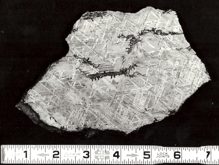
Displays of meteorites in museums generally consist of large, solid chunks of iron meteorites and of etched slices, as shown in Figures 2 to 6. These slices are ground smooth and then etched with a strong acid solution that brings out the growth structure. The octahedrites are commonly exhibited in this manner because they undergo a solid-state phase transformation where the kamacite (ferrite) nucleates and grows along the octahedral planes of the parent taenite (austenite) phase producing a beautiful etched pattern.
The growth of the kamacite phase in octahedrites occurs very slowly. Based upon the known rate of diffusion of nickel in iron, the cooling rate between about 700 and 400ºC, where the transformation occurs, has been found to vary from about 1 to 250ºC per million years! So, no graduate student, no matter how dedicated, can reproduce these macro- and microstructures in the laboratory!
It is important to examine the gross macrostructure (the structure revealed by etching a large ground section and viewing it with the unaided eye, or at low magnification) but much more information can be obtained by microscopical examination of polished and etched specimens. Because iron meteorites are opaque to light, they must be examined with a reflected light microscope, as used by metallographers in the study of man-made metals, such as irons and steels. Indeed, techniques for ferrous alloys work very well for Fe-Ni meteorites.
Microstructures
Iron meteorites are Fe-Ni alloys with nickel contents ranging from about 4.3 to 34 weight %. Most, however, have nickel contents from about 5 to 10%. Small amounts of cobalt are also present, generally from about 0.4 to 1.0%. Sulfur, phosphorus, and carbon are also present but their amounts are quite variable. Trace levels of many other elements may be detected.
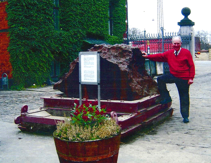
![Figure 3: This 375 kg mass from the Canyon Diablo fall is at Yale University. The surface is well preserved and is typical of many recovered pieces. Photo courtesy of Dr. Vagn Buchwald [1].](https://vacaero.com/wp-content/uploads/2018/06/375-kg-mass-from-the-Canyon-Diablo.gif)
The three basic types of Fe-Ni meteorites are defined by the bulk nickel content, and by the width of the kamacite phase in the octahedrites. Hexahedrites are single crystals of kamacite, that is, no grain boundaries are observed even in quite large specimens (the largest ones found on earth are about 20 feet in diameter). Hexahedrites usually have nickel contents in the range of 5.2 to 5.8 weight %. Other phases, chiefly iron-nickel phosphides, occur in hexahedrites; hence, not all of the nickel is in solution in the kamacite (ferrite) phase.
Octahedrites contain about 5 to 10 weight % Ni, and two main phases – kamacite and taenite (austenite). Upon solidification, taenite forms. With subsequent cooling, kamacite is nucleated on the octahedral planes of the taenite and grows in a preferred pattern. The kamacite that forms is lower in nickel content, generally about 5.5 to 7.5%, than the bulk Ni content. Thus, there is a movement of nickel atoms with the remaining taenite phase becoming enriched in nickel. As the bulk nickel content increases, the bandwidth of the kamacite grains decreases. Octahedrites are classed in five steps from coarsest (lowest Ni) to finest (highest Ni) and then plessitic (distinct bands no longer exist).
![Figure 4: This 350 kg piece from Gibeon is at the Max-Planck-Institut in Heidelberg. It is also well preserved and exhibits the same characteristics as the Canyon Diablo piece in Fig. 2. The ruler at the base of the mass is 15 cm long. Photo courtesy of Dr. Vagn Buchwald [1].](https://vacaero.com/wp-content/uploads/2018/06/350-kg-piece-from-Gibeon.gif)
Octahedrites also contain two-phase mixtures of kamacite and taenite known as plessite. The morphology of these mixtures varies, and their amount increases, with increasing nickel content. A wide variety of rather colorful jargon has been created to describe these different plessitic patterns.
Ataxites contain higher nickel contents that octahedrites, frequently in the 15 to 18% range. Unlike the octahedrites, they do not exhibit gross macrostructural patterns. Relatively few ataxites have been found. The kamacite in ataxites is equiaxed, that is, approximately equal in size in all directions. Also, their grain diameter is small, about 30 µm or less. Kamacite grains in octahedrites are quite long (up to several centimeters is not unusual) and narrow. Length-to-width ratios of 10 to 30 are commonly observed.
![Figure 5: The 20 ton Agpalilik mass of the Cape York meteorite (one of 4 massive pieces found) was sectioned in October 1970 using a wire saw fed through a carborundum water slurry. Two cuts were made, 5 cm apart, each requiring about 195 hours to complete. The area was ~1.4 sq. m and weighted 560 kg. Six additional pieces were cut weighing from 428 to 893 kg over a 760 h period. The lower half of the above slab was ground, polished and macroetched and can be seen at the Mineralogical Museum of Copenhagen. Photo courtesy of Dr. Vagn Buchwald [1].](https://vacaero.com/wp-content/uploads/2018/06/20-ton-Agpalilik-mass-of-the-Cape-York.gif)
The kamacite phase in meteorites has a body-centered cubic crystal structure identical to that of α-iron in steels. Taenite has a face-centered cubic crystal structure identical to that of γ-iron in certain types of stainless steels. When kamacite is deformed, as in extraterrestrial impacts between asteroids, twinning occurs if the rate of strain is high (as in a collision) and the temperature is low (as in outer space). These twins are called Neumann bands and they are ubiquitous in kamacite in hexahedrites and octahedrites, unless recrystallization has occurred due to reheating. Neumann bands are not commonly observed in ataxites unless the grain size is rather large. Neumann bands are long (up to several cms is possible) and narrow (1-10 µm).
When kamacite forms and grows in the octahedrites, thin films of residual taenite can be observed between portions of some of the adjacent kamacite grains. Also, wedge-shaped patches of taenite can be observed at kamacite grain junctions. If these patches are relatively large, greater than about 50 µm in diameter, martensite may form in the central region where the nickel content is less than 25%. The nickel content of these taenite patches is highly variable. At the extreme surface, adjacent to the kamacite, nickel contents of about 50% occur in a very thin zone, 1-2 µm wide. Below this thin layer the nickel content gradually drops to about 28 to 30%. This zone is called the “cloudy” zone because of its appearance after etching with nital. Beneath this zone, the nickel content continues to decrease until martensite is observed when less than 25% is present. The structure of these regions is very complex. Transmission electron microscopy is required to study it properly.
![Figure 6: A macroetched slice from Gibeon displaying the original taenite grain boundaries (G.B.) and elongated troilite inclusions (FeS). The lower right corner displays severe plastic deformation possibly caused during the fall. The scale bar below the photograph is 2 cm. Photo courtesy of Dr. Vagn Buchwald [1].](https://vacaero.com/wp-content/uploads/2018/06/macroetched-slice-from-Gibeon.gif)
Carbides can be observed in certain meteorites, but not all. The most common carbide in meteorites is called cohenite with the general formula (Fe, Ni, Co)3C. This basic type of carbide occurs in steels and is called cementite (with the general formula M3C where M refers to a metal, mainly Fe, but also the substitution of small amounts of Mn and Cr), but cementite in steels never contains Ni or Co. An alloy carbide, called haxonite, has been observed in a few meteorites. Both carbide types are very hard.
Phosphorus is very common in meteorites, but in much greater concentrations than in steels. When the phosphorus level exceeds about 0.06 weight %, which is quite common in meteorites, phosphides are formed. They have a tetragonal type crystal structure with the general formula (Fe, Ni)3P but different morphologies are observed. Schreibersite is the name given to globular shaped phosphides in meteorites. Their size is a function of the phosphorous content. Schreibersite has a variable nickel content, depending upon the temperature at which they nucleated, from about 10 to 50% Ni. The higher nickel content particles tend to be smaller in size and they are more ductile than the larger, lower Ni particles, which are often cracked.
Rhabdites are phosphides that have plate-like or prismatic shapes. These types of phosphides are most common in hexahedrites. In most instances, the prismatic-shaped particles are crack free but the plate-like shaped particles exhibit numerous transverse cracks.
Many other mineral phases have been found in meteorites but they are much less common than those discussed above. Also, these phases may be rather erratically distributed within a given meteorite, rather than being uniformly distributed. These microstructures will be illustrated in subsequent articles on meteorites in this column.
Metallographic Techniques
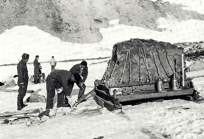
Techniques that have been developed for iron and steel specimens are directly applicable to meteorites. Sections must be removed from the parent mass with as little damage as possible. This may be difficult to achieve when very large masses must be sectioned (see Figure 1 and also Part I of this article). The gross macrostructure of meteorites can be very dramatic, as shown in Figure 2. Octahedrites obtained their name from this very striking macrostructural growth pattern of the kamacite (ferrite) phase, which is visible to the unaided eye. Octahedrites generally contain from ~5 to 10 weight percent Ni. The as-solidified microstructure is FCC taenite (austenite). With subsequent cooling, kamacite nucleates on the prior-taenite grain boundaries producing the Widmanstatten pattern shown in Figure 8. Determination of the prior-taenite grain size has been rarely done due to the need for exceptionally large specimens. Vagn Buchwald, in his study of the 20,140 kg Agpalilik Cape York meteorite (Figure 7), measured a prior-taenite grain size of ~2 X 1.5 X 1.5 m – yes, meters, not millimeters!
Cutting does deform the microstructure adjacent to the cut surfaces. Heat is also generated during cutting and this can alter the microstructure. Thus, a cutting procedure that produces as little damage as possible must be chosen and properly implemented. After sectioning, small pieces may be embedded within a polymer compound for convenience in holding, either by hand or within a fixture. Automated grinding and polishing equipment has become very common in metallographic laboratories and some machines can accommodate unmounted bulk specimens, even with rather large sizes.
In most work, a surface is selected for the examination and it is subjected to a series of grinding operations with progressively finer abrasives. Fixed abrasives, as for SiC grinding paper, is most commonly utilized. In the traditional approach, grinding progresses from a reasonably coarse SiC particle size, e.g., 120-grit, down to a 600 (P1200) grit finish, that is, a SiC particle size of about 15 μm. Modern procedures used by the writer use one or two SiC steps because sectioning was done with a device, such as the Secotom saw, that produces minimal damage. The first SiC step is with an abrasive that will get the specimens in the holder co-planar with minor effort while removing the sectioning damage. But, the grit size is not so coarse that the grinding introduces more damage than cutting did. Generally, a grit size of 180 is adequate. A second grind with 220- or 240-grit SiC is adequate.
After the various grinding steps are completed, specimens are polished using a series of progressively finer abrasives. The most common coarse polishing abrasive is diamond. One or more steps are used, e.g., 9- and 3-µm, and occasionally 1- µm diamond. Generally, diamond is applied to a cloth covering a rotating wheel. Numerous types of cloths may be utilized. Generally, for coarse diamond sizes a low-nap or napless cloth is used, such as a hard-woven polyester, silk or nylon. Fine diamond sizes may be used on a low-nap cloth or a synthetic, napless cloth. Diamond abrasives finer than 1 µm in size are not commonly used.
Final polishing may involve one or more steps, depending upon the material being polished, equipment availability, number of steps with diamond abrasives, personal preference, etc. Aqueous slurries of graded α- or γ- alumina (0.3- or 0.05-μm diameter, respectively) may be used. The writer prefers to final polish specimens using colloidal silica, a solution with a pH of about 10 containing very fine (~0.05 μm), spherical amorphous silica particles, or with agglomerate-free 0.05-µm diameter alumina made by the sol-gel process; a neutral pH (as with OP-AN) helps minimize staining problems. Final polishing can be done using a rotating wheel.
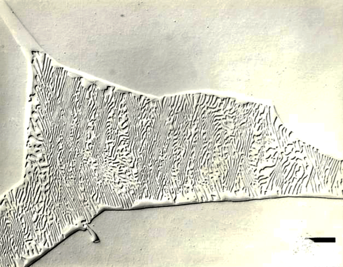
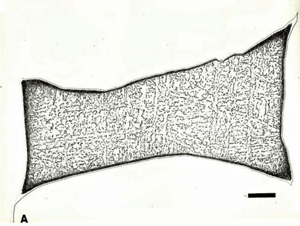
After polishing, specimens should be examined with the reflected light metallurgical microscope to evaluate the preparation and detect any constituents that are “dark” without etching. Incident bright-field (BF) illumination is most commonly employed. Without etching, very little can be observed of the microstructure, unless differential interference contrast (DIC) illumination is employed. BF examination of the as-polished specimen will detect cracks, terrestrial corrosion and certain second phases (graphite, sulfides, silicates, etc.). If a small amount of relief is developed during polishing, DIC can reveal the plessite constituent, Figure 3, and phosphides and carbides very well. This shows plessite in Odessa, a coarse octahedrite that fell in Texas (meteorites are named after the town or post office closest to the fall site). Octahedrites are classified by the width of the elongated kamacite grains. Spearman, shown in Figure 2, is a medium octahedrite while Gibeon, Figures 9 and 10, is a fine octahedrite. Kamcite forms from taenite in meteorites along the octahedral planes. The kamacite growth rate is exceptionally slow – estimates vary from 1 to 250 °C per million years! So, no graduate student can duplicate these microstructures in the lab! Length-to-width ratios are typically in the range of 10 to 30.
In nearly all cases, etching is needed to properly reveal the microstructure, just as for most man-made metals and alloys. This is essentially a controlled corrosion process. Etchants may be acidic or basic and they may contain various chemicals designed to increase the attack rate. The corrosion rate of metals varies with crystal orientation. In a polycrystalline metal, the crystal planes within each grain have a specific orientation and this orientation differs from grain to grain. Because corrosion rates are sensitive to crystal orientation, each grain is dissolved at a different rate which, if controlled, permits the grain structure to be revealed.
In like manner, the corrosion rate at a grain boundary is different, usually higher, than within the grain due to energy differences. One type of phase may be attacked at a different rate than another. The presence of alloy or impurity segregation or variations in residual or applied stresses also influences the local corrosion rate. All of these factors enable an etchant to reveal microstructural details. Polarized light has rather limited applicability in the study of meteorites as only a few constituents are optically anisotropic.
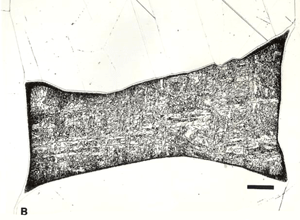
The most commonly used chemical etchants for meteorites, which are also the most commonly used etchants for steel, are nital and picral. Nital is a solution consisting of 1 to 4% nitric acid in ethanol. Picral is a solution consisting of 4 g picric acid dissolved in ethanol. Both etchants dissolve the kamacite (ferrite) phase preferentially to other phases. Nital, however, is quite sensitive to the crystallographic orientation (as with steels) of the kamacite while picral is not. Hence, picral dissolves the kamacite uniformly while nital does not. Nital will reveal kamacite grain boundaries but picral will not. Picral does not reveal the Neumann bands or as-formed martensite. Nital reveals both well. Nital is preferred for the overall study of the microstructure of meteorites although picral is good for examining the plessitic structures. As an example, Figure 10 shows views of the same patch of plessite in Gibeon, a fine octahedrite that fell in Southwest Africa. Picral, Figure 10a, reveals the very fine taenite (austenite) particles within the patch. Note that there is a thin band of white taenite around the outer edges of the patch. Just inside the edge is a dark etching zone of “black” plessite, a very fine mixture of kamacite and ferrite. Within the plessite patch, we observe very fine particles of taenite in a kamacite matrix. Etching with nital, Figure 10b, reveals grain boundaries within the kamacite matrix of the plessite which obscures the fine taenite particles. Note that some Neumann bands and some subgrain boundaries can now be observed in the kamacite surrounding the plessite. We should point out that kamacite and taenite were named by Reichenbach in 1861 – 2 years before Sorby first observed metallographically prepared steel and iron specimens.
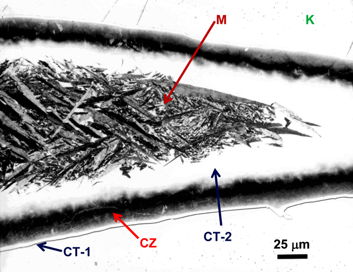
Figure 11 shows an example of a large patch of taenite between kamacite (K) grains where the nickel content was low enough in the center for martensite to form. At the very edge of the taenite wedge, there is a thin layer of “clear” (retained) taenite (CT-1) where the nickel content is about 50% – this is an ordered Fe-Ni phase. Below, this is a dark etching band called the “cloudy zone” which actually contains two phases, ordered Fe-Ni with ~50% Ni and very fine martensite with ~12% Ni (only resolvable with the transmission electron microscope). The bulk Ni content is ~28-30%. The cloudy zone (CZ) has a bluish/brownish color when etched with nital. Between the cloudy zone and the martensite central area is the second region of “clear” (retained) taenite (CT-2) where the nickel content continues to decrease. Martensite is not always found in the wedge-shaped patches of taenite. It is usually seen in large taenite patches, greater than 50 μm in diameter, and in areas where the nickel content is <25%.
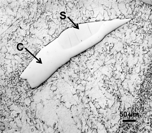
Carbides can be observed in some Fe-Ni meteorites, but not all. The most commonly observed carbide is called cohenite (no, it was not named after the late Morris Cohen) with the general formula (Fe, Ni, Co)3C. It is similar to M3C carbide in steels, called cementite, but Ni and Co are never seen in cementite in steels. The M stands for (Fe, Mn, Cr) in cementite. An alloy carbide called haxonite has been detected in a few meteorites. Figure 12 shows an example of cohenite in Canyon Diablo, a coarse octahedrite that fell in Arizona.
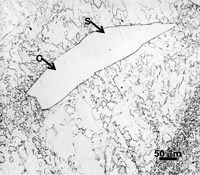
Phosphides are frequently observed in meteorites. Canyon Diablo contains 0.26% P and Figure 12 shows schreibersite with internal cracks. The phosphides are tetragonal with the general formula (Fe, Ni)3P. Schreibersite is the name for the more globular shaped phosphides and their size is a function of their P content. The Ni content also varies depending upon the temperature of the meteorite when they nucleated. High Ni content schreibersite particles tend to be smaller and more ductile while low Ni content particles, such as this one, usually have low Ni content and are often cracked. Rhabdites are phosphides that are small and have plate-like or prismatic shapes, as shown in Figure 13. The prismatic-shaped rhabdites are usually crack-free while the plate-like particles often are cracked. Figure 14 shows sphalerite, ZnS with a cubic crystal structure, also detected in Canyon Diablo.
Comments
For the absolute best source of information about meteorites, look for copies of Vagn Buchwald’s three-volume masterpiece, Handbook of Iron Meteorites published in 1975 by the Center for Meteorite Studies, Arizona State University and the University of California Press. The next part in my presentation on Fe-Ni meteorites will be devoted to the use of color etching to reveal the microstructure of meteorites.
Color Metallography
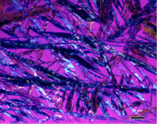
There are virtually no cases of naturally occurring color in meteoritic microstructures. Color can be introduced using DIC but it has no physical significance or value. Polarized light may produce some color effects with graphite and certain mineral phases but these are not commonly observed. Crossed polarized light, in some instances, can produce color effects in coarse martensite within taenite wedges, as shown in Figure 15. This is a high magnification micrograph of coarse martensite in Odessa using nearly crossed polarized light and a sensitive tint plate (which has colored the residual taenite magenta).
The best approach to create meaningful color micrographic images is to “tint” etch the specimen, sometimes after performing a light etch with picral or nital. A tint etch [1] produces a stable film on the specimen surface whose thickness depends upon the composition (and variation in composition) of the phase, its crystal orientation, the presence of residual strain, and etch time. Tint etchants are classified as being anodic, cathodic or complex, depending on the nature of the film that forms. Anodic tint etchants, the most common type, produce films over the matrix phase, such as kamacite in meteorites. Cathodic tint etchants produce films over the second phase constituents, such as cohenite. Complex tint etchants will produce films over both matrix and second phases (but not necessarily over all types of second phases present).
Tint etchants are aqueous or alcoholic solutions that are balanced to produce a thin film on the specimen surface, typically 40 to 500 nm thick, of an oxide, sulfide, complex molybdate, chromate or elemental selenium. Colors are developed by interference in the same manner as films produced by heat tinting or by vacuum deposition of a dielectric compound with a high index of refraction (the Pepperhoff method). The film thickness controls coloration. As the thickness increases, at a certain thickness interference begins and colors are produced, beginning with yellow, then green, red, violet, blue and silver. Both the first order and second order colors can be observed as the film grows.
With the cathodic tint etchants, the film only forms over the second-phase particles and the films are usually relatively constant in thickness with etch time. In some cases, the color is rather constant which suggests that it grows to some specific thickness and then stops. With the complex tint etchants, the same colors may, or may not, be observed only with certain second phases. The matrix phase may be colored according to crystal orientation and some grains may have the same color as some of the second phases. One must be careful in interpreting phases with the complex reagents. Interpretation is easier with the anodic and cathodic tint etchants.
Experiments have shown that certain tint etchants that work well with carbon and alloy steels do not color meteorites. This is due to the compositional differences between meteorites and ordinary steels. For example, Klemm’s I is a very popular anodic tint etch that will color ferrite in carbon and low-alloy steels. However, it is difficult to color kamacite (ferrite) in most meteorites because of their high nickel content. The lower Ni hexahedrites can be colored using Klemm’s I, but it is easier to color them if you double the potassium metabisulfite content, or use Klemm’s II or III. Beraha’s sodium molybdate cathodic tint etch will color cementite (Fe3C) in carbon and low- alloy steels, even if some manganese or chromium is dissolved in the cementite (replacing some of the iron). However, it will not color cohenite (Fe, Ni, Co)3C, in meteorites. What works and what doesn’t work can only be determined by experimentation.
Specimen preparation prior to tint etching must be of the absolute highest quality, otherwise, tint etch results will be very poor. A polished specimen that appears to be scratch free when viewed with bright field may exhibit a dense scratch pattern (from residual preparation-induced damage) after tint etching.
Many of the tint etchants that metallographers use were developed by the late Israeli metallographer/chemist Emanual Beraha. Several of his tint etchants deposit a thin sulfide film on a wide range of metals and alloys. These films are produced in two ways. For solutions that contain either potassium or sodium metabisulfite, the iron, nickel or cobalt cation in the sulfide film comes from the specimen while the sulfide anion comes from the reagent after it decomposes. The other sulfide film type is produced by a metal-thiosulfate complex in the reagent, an aqueous solution of sodium thiosulfate, citric acid, and cadmium acetate or cadmium chloride. The specimen acts as a catalyst and the film that forms is cadmium sulfide.
The tint etchants are used by immersion, that is, the polished specimen is placed face up in a container holding about 100 mL of the solution. Swabbing of the surface with a cotton tuft soaked with the solution is never performed as the film will not form under such conditions. Etch time varies between about 45 and 300 seconds, depending on the solution used.
Color Metallographic Examples
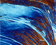
One of the simplest color etchants is an aqueous solution of 10% sodium metabisulfite (Na2S2O5). This solution can be used to tint etch most carbon and alloy steels, including the ultra-high strength, ultra-high toughness, Ni-Co steels. To get good color effects, it is necessary to view the specimen with nearly crossed polarized light and a sensitive tint plate. Figure 16 shows the microstructure of Odessa etched with this solution and viewed in this manner. In the lower right corner, there are patches of plessite which, because of the lamellar pattern of the kamacite and taenite, respond brightly. In the upper and lower left side, we see pink phosphides (schreibersite) containing cracks. They are pink because of the sensitive tint plate used with nearly crossed polarizers; in bright field, they would be white. The matrix consists of several kamacite grains colored light violet, purple and blue. Note that there are numerous straight or slightly curved red lines in the kamacite. These are Neumann bands from extraterrestrial shock events. In the blue kamacite region, some very faint Neumann bands can be seen. These are probably from much older shock events. Also in the blue kamacite, we observe a series of fine blue lines that are interconnected. These are subgrain boundaries. A few very small phosphides are observed on these lines. Note also that there is a variation in the blue region of kamacite on the left half of the micrograph. This is from either chemistry variations or from residual stress in this area.
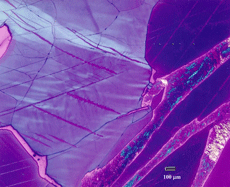
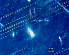
Figure 17 shows the microstructure of Coahuila, a hexahedrite that fell in Mexico. It was etched with an aqueous solution containing 10% sodium thiosulfate (Na2S2O3) and 3% potassium metabisulfite (K2S2O5) and is viewed with bright field. As for nearly all hexahedrites, the Coahuila specimen is a single crystal, that is, the kamacite matrix has no internal grain boundaries. Note that all of the kamacite is colored blue. There are a number of parallel light blue lines running diagonally left to right. These are Neumann bands. The white particles are phosphides, both prismatic and plate-shaped (in three dimensions). Note that one prismatically-shaped rhabdite in the lower right corner has cracked due to two intersecting Neumann bands. Note also the variation in color around the large prismatically-shaped rhabdite in the center of the image. This is due to compositional variations around the phosphide. The kamacite background has a rough appearance due to the presence of many very small (<1 μm diameter) phosphides.
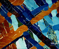
Figure 18 shows Gibeon, a fine octahedrite that fell in Southwest Africa ~50,000 years ago, after color etching with this same solution. Being a fine octahedrite, the kamacite bandwidth is fine enough that a low magnification photograph can show how the coloring of a matrix phase, much as kamacite, varies with crystal orientation. Note that the structure exhibits elongated kamacite grains colored various shades of brown and blue. Fine, parallel Neumann bands are observed within each kamacite grain. The white films between the kamacite grains are taenite. Note also a number of different types of plessite patches between kamacite grains.
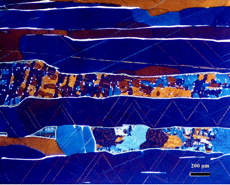
Figure 19 shows another view of Gibeon, using the same etch, showing two parallel bands of plessite of several types running horizontally across the field of view. Note the white films of taenite at plessite-kamacite or kamacite-kamacite boundaries. The fine lines in the kamacite matrix are Neumann bands.
Figure 20 shows the microstructure of Henbury, a medium octahedrite that fell in Australia after etching with sodium thiosulfate and potassium metabisulfite. This meteorite was subjected to a violent event that ripped it apart, probably in outer space. The structure is mostly highly deformed kamacite containing many fine mechanical twins (Neumann bands). In the upper right corner, we see a large phosphide.
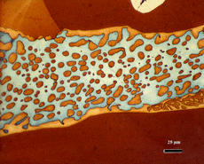
Beraha’s complex thiosulfate tint etch that forms a cadmium sulfide interference film works very well with meteorites. Figure 7 shows the microstructure of Arispe, a coarse octahedrite that fell in Sonora, Mexico, tint etched with Beraha’s CdS reagent. This shows a high magnification view of plessite in Arispe where both kamacite and taenite are colored. Surrounding the plessite, we observe kamacite colored brown. In the upper right corner, some non-colored cohenite is present. At the edge of the plessite, there is a tan rim of taenite. The kamacite within the plessite is light blue while the taenite particles in the plessite are tan.
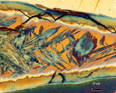
Figure 21 shows a taenite wedge in Odessa (similar to that shown in Part II) after tint etching with Beraha’s CdS reagent. The surrounding kamacite is yellow at the top and contains reddish Neumann bands. At the edge of the taenite wedge, there is a very thin light blue film, the outer clear taenite (CT1) zone. Next to this is the cloudy zone where the color varies across the zone as the nickel content decreases. Next to this is a white zone of clear taenite (CT2) and in the center, we see bluish plates of martensite (Ni <25 wt. %) surrounded by yellow-tan colored kamacite.
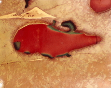
As a final example, Figure 22 shows the microstructure of Canyon Diablo etched with Beraha’s selenic acid tint etch. There is no fixed composition to this reagent. It consists of hydrochloric acid (up to 20 mL), selenic acid (up to 3 mL) and ethanol (amount added so that the total is 100 mL). One must experiment to find the best composition. Pre-etching with nital is required for best results. Figure 23 shows two patches of cohenite colored orange-brown. Note that in the center of the field, there are greenish patches of schreibersite attached to the cohenite. The cream and tan patches are taenite. The matrix is highly deformed kamacite containing some faint subgrain boundaries.
Conclusions
Color metallography adds an extra dimension to the study of the microstructure of meteorites. Tint etchants are very sensitive to phase composition and to other effects, such as crystal orientation. However, unlike nital where the strength of the attack varies with crystal orientation so that not all of the structure is properly revealed, tint etchants show crystal orientation differences by variations in color. Phase identification is usually much easier using tint etchants. There are a number of tint etchants that will selectively etch only certain second phase constituents, thus aiding in their identification without need to use expensive electron beam analytical methods. Tint etchants are also sensitive to chemical analysis variations or the effects of residual deformation while the standard “black and white” etchants are not.
References
1. Vagn F. Buchwald, Handbook of Iron Meteorites: Their History, Distribution, Composition and Structure, three volumes, Center for Meteorite Studies, Arizona State University and the University of California Press, Berkeley, 1975.
[1] G.F. Vander Voort, “Color Metallography,” in Vol. 9, Metallography and Microstructures, ASM Handbook, G. F. Vander Voort (ed.), ASM International, Materials Park, Ohio, 2004, pp. 493-512.George Vander Voort has a background in physical, process and mechanical metallurgy and has been performing metallographic studies for 50 years. He is a long-time member of ASTM Committee E-4 on metallography and has published extensively in metallography and failure analysis. He regularly teaches MEI courses for ASM International and is now doing webinars. He is a consultant for Struers Inc. and will be teaching courses soon for them. He can be reached at 1-847-623-7648, EMAIL: georgevandervoort@yahoo.com and through his web site: www.georgevandervoort.com
To View a listing of all George’s articles please click here
Read George Vander Voort’s Biography

