March 9, 1862 marks the date when the USS Monitor and the CSS Virginia (formerly the USS Merrimack) fought an indecisive naval battle at Hampton Roads that changed naval warfare from wood and sails to iron and steam. The USS Monitor sunk off the Outer Banks of North Carolina during a storm on December 31, 1862 but its remains were discovered in 1973. The wreck site, the Monitor National Marine Sanctuary, is managed by the National Oceanic and Atmospheric Administration (NOAA).
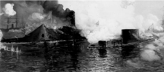 |
| The Battle at Hampton Rhodes, the USS Monitor is on the right. |
The Confederates began construction of an “ironclad” ship at the Gosport Yard of Hampton Roads in 1861. This was well known to the Union Navy Department. The US Army had actually launched ironclad gunboats in the summer of 1861 to patrol the Mississippi River; but none were available in the east to counter the Virginia. On August 3, 1861, Gideon Wells (Secretary of the Navy) requested design proposals for ironclad warships. Swedish inventor John Ericsson had designed an ironclad in 1854 for Napoleon III that incorporated a revolving cupola turret. Cornelius Bushnell promoted this design to Abraham Lincoln. Ericsson was given the contract – but he had to complete the vessel in only 100 days in order to be paid ($275,000)! The vessel was constructed at the Continental Iron Works in Greenpoint, New York. The government contract was signed on October 4, 1861. Thomas Fitch Rowland of the Continental Iron Works agreed to roll the hull material at $0.07 per pound. Manufacture of plates, castings and fittings were subcontracted to eight ironworks and foundries, including Holdane & Co., Albany Ironworks and Rensselaer Ironworks of New York while four companies, including H. Abbott & Sons of Baltimore rolled the 1-inch thick plate for the turret. Delamater Iron Works of New York City constructed the engines and boilers, including the propeller shaft. On December 30, the boilers were fired up and the steam engine was tested.
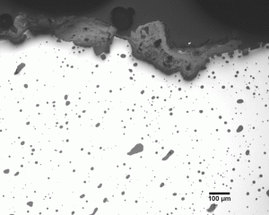
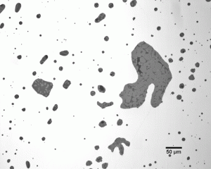
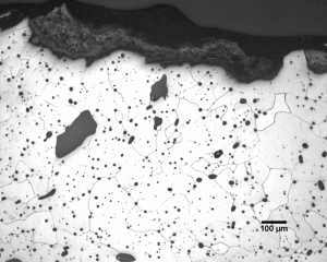
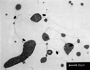
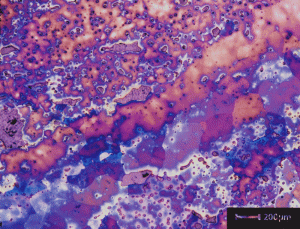
The piece from the propeller shaft was provided by The Mariner’s Museum, Newport News, Virginia. It was made from wrought iron and the section provided was transverse to the shaft axis. Many small slag particles are observed (Figure 1). The ferrite grain size is reasonably fine, but two areas with coarser grains were observed. These appeared to contain fewer slag particles to inhibit grain growth. The ferrite appears to be quite uniform in composition and has less segregation within these areas than in the rest of the cross section. The hardness was 117 HV. Micrographs are shown after etching with 2% nital for grain size (Figure 2), 4% picral to detect cementite (Figure 3), and with three tint etchants (Klemm’s I, 10% sodium metabisulfite and Beraha’s sulfamic acid etch No. 1) to evaluate the uniformity of grain size and composition (Figure 4). Note that Klemm’s I, which normally works best for revealing ferrite grains, revealed the phosphorous segregation so strongly that individual grains are not easily observed. The other two color etchants were much less sensitive to the phosphorous segregation.
George Vander Voort has a background in physical, process and mechanical metallurgy and has been performing metallographic studies for 47 years. He is a long-time member of ASTM Committee E-4 on metallography and has published extensively in metallography and failure analysis. He regularly teaches MEI courses for ASM International and is now doing webinars. He is a consultant for Struers Inc. and will be teaching courses soon for them. He can be reached at 1-847-623-7648 1-847-623-7648, EMAIL: georgevandervoort@yahoo.com and through his web site: www.georgevandervoort.com
To View a listing of all George’s articles please click here
Read George Vander Voort’s Biography

