Abstract
Metallographic techniques for cast irons are similar to those for steels; with the exception that graphite retention is a more challenging task. Recommended procedures to prepare cast irons are given. Colloidal silica is an excellent final polishing abrasive for many metals and alloys. However, for pearlitic cast iron grades, colloidal silica often produces small etch spots on the specimen surface. In this case, OP-AN alumina suspension yields excellent results, much better than standard alumina abrasive powders made by the calcination process. Examples of cast iron structures revealed using a variety of etchants is presented.
Introduction
New concepts and new preparation materials have been introduced that enable metallographers to shorten the process while producing better, more consistent results. But first, the specimens must be sectioned. Many metallographers do not use a blade designed for metallography work, and the depth of damage will be much greater when production-type abrasive saws are used. So, as a first rule, produce a cut with the least possible amount of damage. If an automated device is used that holds a number of specimens rigidly (central force), then the first step must remove the sectioning damage on each specimen and bring all of the specimens in the holder to a common plane. This first step is often called “planar grinding.” SiC paper can be used for this step, although more than one sheet may be needed. Alternatively, the metallographer could use MD-Piano 120 or 220 (for specimens with hardness >150 HV) for the initial grind, followed (if desired) by MD-Piano 600 for a second grinding step. If the cast iron has a low hardness (<250 HV), one can planar grind with MD Primo 220. Alternatively, MD-Allegro could also be used to planar grind for specimens >150 HV hardness. If the hardness is <150 HV, MD-Largo can be used.
One or more steps using diamond abrasives on napless surfaces usually follow planar grinding. PSA-backed or magnetic disc cloths are widely used. These give good cutting rates, maintain flatness and minimize relief. Cloths, such as MD-Dur and MD-Dac cloth, provide the best flatness and excellent surface finishes relative to the diamond size used. MD-Plan cloth is somewhat more aggressive and gives nearly as good a surface finish, and similar excellent flatness. MD-Dac gives excellent flatness and is excellent with finer diamond sizes, 3 µm and under. Diamond suspensions are popular with automated polishers as they can be added easily during the polishing cycle; although it is still best to charge the cloth initially with diamond paste of the same size to get polishing started quickly. Final polishing is performed using either OP-S colloidal silica or with OP-AN alumina slurry using napless, or low- to medium-nap cloths. Contra rotation (head moves in the direction opposite to the platen) is preferred as the slurry stays on the cloth better, although this will not work it the head rotates at a high rpm. If the head rotates >100 rpm, the slurry may be splattered all over the operator and walls using contra rotation.
Preparation Methods
Iron-based alloys account for a large portion of all metals production. The range of compositions and microstructures of iron-based alloys is far wider than any other system. Development of scratch-free and deformation-free grain structures in low hardness cast irons (ferritic or nearly fully ferritic matrix structures) is difficult. Cast irons may contain graphite, which must be retained in preparation. Preparation of ferrous metals and alloys is quite straightforward using the contemporary methods. Edge retention, graphite and inclusion retention are excellent, especially if automated equipment is used. The following procedures, Tables 1 and 2, are recommended and are adequate for the vast majority of cast ferrous metals and alloys.
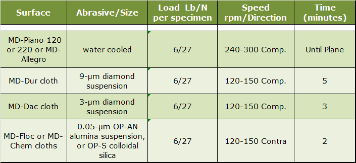 |
| Table 1. Four-Step Practice for Hard Cast Irons. |
This practice is useful for all cast iron specimens, including graphitic cast irons. It is preferred for cast irons with harder matrix phases and second phases. Instead of using SiC, diamond discs such as the MD-Piano 120 or 220 or the MD-Allegro can be used and they produce superb flatness and graphite retention. If the grade being prepared is particularly difficult to prepare perfectly, add a 1-µm diamond step, before the final polish, using either MD-Dac or MD-Sat cloths with the same parameters as the 3-µm step. Due to their high silicon content and the potential for staining problems, it is best to use the OP-AN alumina suspension for the final polishing step. Colloidal silica can produce small etch spots on pearlite patches in cast irons, so it is best avoided if the matrix is pearlitic. For ferritic or martensitic grades, colloidal silica works fine. If the cast iron is particularly low in hardness, such as those with fully ferritic matrices, it is better to use the MD-Primo or MD-Largo discs, ideal for softer grades.
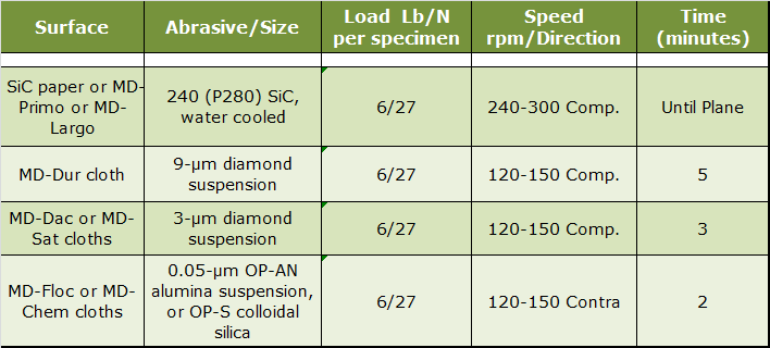 |
| Table 2. Four-Step Practice for Soft Cast Irons. |
For difficult grades, a 1-µm step can be added before the final polishing step, as mentioned above.
Etchants
Metallographic etching encompasses all processes used to reveal particular structural characteristics of a metal that are not evident in the as-polished condition. Examination of a properly polished specimen before etching may reveal structural aspects such as porosity, cracks, and nonmetallic inclusions. Indeed, certain constituents are best seen and measured by image analysis without etching, because etching will reveal additional, unwanted detail and make observation and detection difficult or impossible. Classic examples of this are the measurement of inclusions in steels and graphite in cast iron.
Etching is done by immersion or by swabbing (or electrolytically) with a suitable chemical solution that essentially produces selective corrosion. It is best to swab using surgical grade cotton that will not scratch the polished surface. Etch time varies with etch strength and can only be determined by experience. For cast irons, either procedure yields equivalent results. In general, for high magnification examination the etch depth should be shallow; while for low magnification examination a deeper etch yields better image contrast. Some etchants produce selective results in that only one phase will be attacked or colored.
The most frequently used etchants for cast irons are 2% nital and 4% picral. These are ubiquitous when dealing with Fe-based alloys. Excellent results can also be obtained using aqueous 10% sodium metabisulfite (10 g Na2S2O5 to 100 mL water). It has many of the common characteristics of nital and picral and is a very safe etchant. Use by immersion at room temperature for 10-20 s. Vilella’s reagent is also useful, particularly with higher alloy grades of cast iron. It consists of 1 g picric acid, 5 mL HCl and 100 mL ethanol. To color cementite selectively, several etchants can be used, but the alkaline sodium picrate solution is one of the best. It consists of 2 g picric acid, 25 g NaOH and 100 mL water. The specimen is immersed in the solution when heated to boiling. It only colors cementite; no other alloy carbide is affected. In alloys containing low amounts of chromium, the Cr will substitute for Fe in cementite. As the level of Cr in cementite increases, it will take more time for the cementite to be colored and this etch will not work when the Cr level gets near the limit (before an alloy carbide of a different formula is formed). Alkaline sodium picrate can also be used electrolytically at 6 V dc, 30 – 120 s, at room temperature. The cementite is usually colored light brown or tan. Iron phosphide can also be colored by several etchants, but perhaps the simplest to use is Murakami’s reagent. The standard version of Murakami’s is adequate: 10 g of either NaOH or KOH, 10 g potassium ferricyanide (K3Fe(CN)6) and 100 mL water. Etch by immersion at room temperature. Etch by immersion at room temperature for 10 – 20 s. Prolonged etching times with either reagent may start to reveal iron phosphide with alkaline sodium picrate or cementite with Murakami’s reagent.
Microstructures
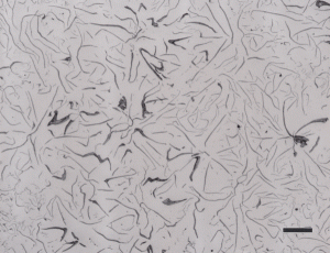
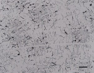
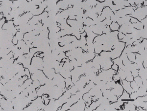
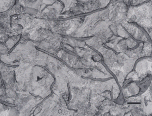
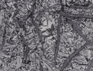
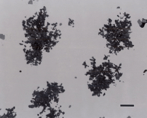
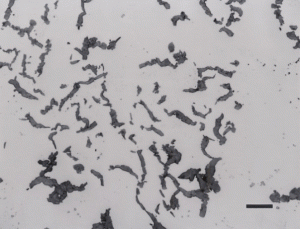
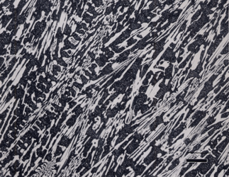
Gray cast iron has an interconnected flake graphite shape. Due to the continuity of the graphite through the structure, and the properties of graphite, gray iron is soft, low strength, but brittle and is easily machined. The flake patterns have been classified into different types by morphology. Figure 1, for example, illustrates type A flakes, Figure 2 shows rosette B type graphite, and Figure 3 shows interdendritic type E graphite in gray iron. These are in the as-polished condition, preferred for examination of graphite. Gray iron can have a variety of structures varying from fully ferritic, Figure 4, to fully pearlitic, Figure 5. As the percentage of pearlite increases, the hardness and strength increase. Occasionally, pearlitic gray iron is heat treated to form martensite, as shown in Figure 6.
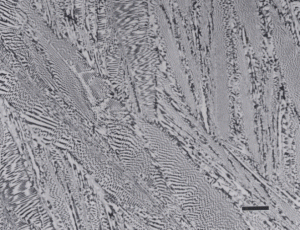
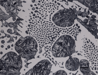
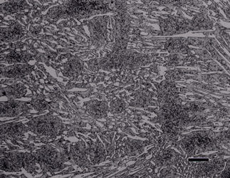
White cast iron is free of graphite with the carbon being present as massive cementite and as cementite in pearlite. The eutectic reaction in the iron-carbon system occurs at 4.3% C and the reaction is liquid transforming on cooling to cementite and austenite. With subsequent cooling the austenite transforms, generally to ferrite and cementite in the form of pearlite. The structure produced by the eutectic reaction is called Ledeburite and is illustrated in Figure 7. A lower carbon content white cast iron microstructure is shown in Figure 8. The most common matrix in white cast iron is pearlite, but martensite can be produced by heat treatment.
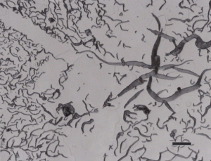
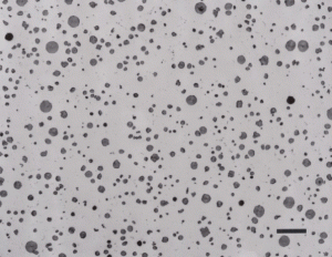
Subjecting a white cast iron to a long-time annealing treatment where the cementite is converted to graphite will produce malleable cast iron. This produces graphite referred to as “temper carbon”, which is illustrated in Figure 9. Another form of graphite is called compacted graphite, as shown in Figure 10, where the continuity of the graphite flakes has been eliminated, producing short flake-like particles. This is an attempt to produce a bridge in properties between flake gray iron and nodular iron (discussed next).
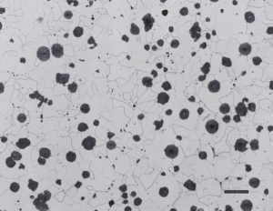
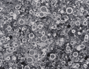
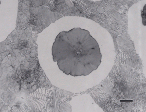
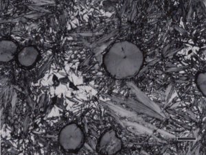
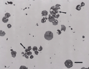
Nodular iron was developed a little over 50 years ago in an attempt to produce greater ductility and toughness in a cast iron by inoculating the melt with reactive elements such as sodium or magnesium. Figure 11 shows well-formed nodules, that is, spheroidal graphite particles in an as-polished specimen. Naturally, the matrix can vary from fully ferritic, Figure 12, to almost fully pearlitic, Figure 13, with a resulting increase in strength and hardness. There will always be a thin band of ferrite, called a ferrite “halo” around nodules due to the depletion of carbon around the growing nodule, Figures 13 and 14. Pearlitic ductile iron can be heat treated to form martensite, as shown in Figure 15. Manufacture of ductile iron is challenging and at times the degree of nodularity can be lower than desired. Figure 16 shows an example of “exploded” graphite nodules, an undesirable condition. Ductile iron can also be austenitized and isothermally transformed producing austempered ductile iron, Figure 17.
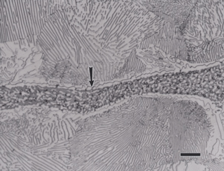
Some unusual constituents can be produced in gray iron and in mottled iron (part gray, part white). The most famous is called Steadite, which is either a two-phase pseudo-binary eutectic (ferrite and iron phosphide) or a three-phase eutectic (ferrite, iron phosphide and cementite). Figure 18 shows an example of the three-phase eutectic of ferrite, cementite and iron phosphide. The iron phosphide has been revealed (darkened preferentially) using Murakami’s reagent at room temperature. Using nital before Murakami’s outlined the ferrite and cementite. This constituent occurs when the phosphorous content is high, above about 0.06%.
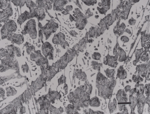
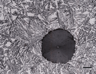
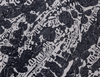
Alloy cast irons can exhibit very interesting structures. As an example, Figure 19 shows as-cast Ni-Hard cast iron etched with aqueous 10% sodium metabisulfite. This revealed the high-carbon plate martensite very well. There is retained austenite visible within the martensitic matrix and the white, continuous phase is carbide. Figure 20 shows another Ni-Hard specimen that was heat treated after solidification and there is much less austenite present. This specimen was etched with Vilella’s reagent and the martensite is dark while the carbide is white. This specimen has a small amount of graphite in the matrix. Finally, Figures 21 and 22 show examples of high alloy cast irons containing martensitic matrices and a large volume fraction of alloy carbides. The specimens were heat treated to produce the martensitic matrices.
Conclusions
This article has described two contemporary approaches for preparing cast iron specimens with a wide range of phases and constituents, as well as different graphite morphologies. First, it is important to use the best possible cutting procedure to minimize the damage in the sectioning plane. This damage must be removed in the first step of the process. If the cutting damage is minimized, then a finer abrasive can be used in the first preparation step. This is important, as the coarser abrasives produce much more damage than the finer abrasives. If, at the end of the preparation sequence, this damage remains, then the true structure will not be revealed. Flat, woven napless cloths are preferred as they maintain surface flatness and are better for retaining second phases, such as graphite.
George Vander Voort has a background in physical, process and mechanical metallurgy and has been performing metallographic studies for 47 years. He is a long-time member of ASTM Committee E-4 on metallography and has published extensively in metallography and failure analysis. He regularly teaches MEI courses for ASM International and is now doing webinars. He is a consultant for Struers Inc. and will be teaching courses soon for them. He can be reached at 1-847-623-7648, EMAIL: georgevandervoort@yahoo.com and through his web site: www.georgevandervoort.com
To View a listing of all George’s articles please click here
Read George Vander Voort’s Biography

