By Dan Herring, THE HERRING GROUP Inc., and Patrick McKenna, Nevada Heat Treating, Inc.
One of the questions all Heat Treaters are asked is, “How much, if at all, will my part change (i.e. shrink or grow) during heat treatment?” While the heat treater would love to be able to give a precise answer to this question, in most situations volumetric size change during heat treatment cannot be accurately predicted, at least not accurately enough to allow for final machining and/or grinding to close tolerances prior to heat treatment.

The answer to the dimensional change question is extremely complicated and involves literally hundreds of variables which include:
- Material grade
- Variation in material properties (chemistry, homogeneity, grain size, number and type of inclusions, and hardenability)
- Part orientation versus grain orientation
- Starting microstructure
- Heat treatments performed at the mill (dozens of variables)
- Manufacturing process and sequence of operations
- Residual stress state (from manufacturing)
- Heat treatment after component manufacturing (dozens of variables)
- Hardness range (initial, final)
In addition, heat-treating itself adds its own unique set of variables, which also may influence part size change. These are:
- Type of process selected (annealing, hardening, nitriding, carburizing, etc.)
- High-heat process (e.g. annealing, normalizing, austenitizing), temperature and soak times
- Low-heat process (age, temper, stress relief), temperature and soak times
- Furnace temperature uniformity
- Furnace repeatability
- Quenchant type
- Quench rate
- Part size
- Load size
- Load configuration
- Part orientation/fixturing
- Type of furnace atmosphere
- Deep freezing or cryogenic processing
- Number of tempering cycles
While a precise forecast of a part’s size change cannot be expected, by considering each of these potential factors, a heat treater can provide a reasonable estimate that can help manufacturing prepare for final machining operations.
Size Change – The Practical Side
Experimental work has been done on many materials to show the effects of heat treatment on size change. As one might expect, the effects are different for every material grade. For example, an 80 mm (3.15”) cube of D-2 tool steel (Fig. 2) reveals growth (0.08%) in one dimension and shrinkage in the other two dimensions as a result of vacuum hardening. This graph demonstrates how knowing the part orientation from the mill-supplied bar is important when trying to plan for size change during heat treatment.
![Figure 2 - [3] - Dimensional Change of D-2 Tool Steel After Hardening (Austenitized at 1020°C (1870°F) for 30 Minutes and Quenched in 2 Bar Nitrogen)](https://vacaero.com/wp-content/uploads/2013/05/figure-1_lg-1.gif)
After tempering, more dimensional changes will occur with D-2 tool steel (Fig. 3). The dimensional changes on hardening and tempering must be added together when trying to estimate total size change. Final part hardness is determined by tempering temperature. Figure 3 demonstrates why the hardness requested by the customer will have a drastic effect on size change.
In another example [4], 17-4 precipitation hardening stainless steel can typically be expected to shrink by 0.0004-0.0006 mm/mm (in/in) when aging from Condition A to Condition H-900 and 0.0018-0.0022 mm/mm (in/in) when aging from Condition A to Condition H-1150.
Case Study
Communication with the heat treater, pre-production trials, and repeatable process controls can help to provide fairly accurate, consistent/repeatable size change estimates.
![Figure 3 [3] - Dimensional Change of D-2 Tool Steel After Tempering](https://vacaero.com/wp-content/uploads/2013/05/figure-2_lg-1.gif)
Recently, a manufacturer embarked on a project to help minimize its post heat treatment machining costs. The company is a tooling manufacturer that designs and supplies round dies made of 440°C stainless steel in sizes ranging from 50mm (2”) diameter x 12.6 mm (½”) thick to 200 mm (8”) diameter x 25 mm (1”) thick. The company’s first step was to meet with the heat treater to discuss its needs. Discussion during the meeting helped to clarify that the amount of size change during heat treatment was not important. What was important was that it be consistent part-to-part, load-to-load and batch-to-batch.
The manufacturer and the heat treater proceeded to list all of the variables that would affect size change during heat treatment. From that list, a shorter list was made of variables that could be controlled during the process. These factors included: the steel supplier (both mill and service center); chemistry; condition of the steel (i.e. grain size, cleanliness, mill treatment practice); manufacturing sequence; heat treatment, and required hardness. Within the heat treatment process, the heat treater committed to precisely controlling the parameters for load size, load configuration (spacing/racking/fixturing), ramp rates, soak times, pre-heat temperature, austenitizing temperature, quench rates and tempering temperature.
By controlling all of these variables, and repeating the process on a weekly basis, the tooling manufacturer is now able to predict the size change during heat treatment of dies (all sizes) to within ± 0.0254mm (± 0.001”), which provides a significant time and cost savings in post heat treatment processing.
The dimensional changes on hardening and tempering should be added together. The minimum recommended machining allowance is 0.15% per side, assuming that stress relief is performed between rough and semi-finish machining, as recommended. If not, machining allowances must be increased accordingly.
Size Change – The Theoretical Approach
When considering size changes during hardening, one must begin by considering the annealed state in which the microstructure consists of ferrite plus cementite. Several reactions occur during hardening. On heating to the austenitizing temperature, formation of austenite and the solution of cementite take place. On cooling from austenitizing temperature, the austenite may transform to martensite, lower bainite, upper bainite, or pearlite depending on the rate of cooling.
The fractional length or volume change associated with any of these reactions can be calculated on the basis of the following general equation:
(1) ΔL/L = ΔV/3VR = (VP – VR) / 3 VR
Where:
ΔV/3VR is the fractional volume change
VP is the volume of the products
VR is the volume of the reactants
Although the formation of austenite from ferrite plus cementite results in a contraction, the formation of martensite from austenite results in an expansion that is usually of larger magnitude and thus a net expansion occurs going from the annealed to the hardened state (100% martensite). The magnitude of this expansion increases with carbon content. In practice, 100% martensite structures are not obtained. Other constituents (such as undissolved cementite, retained austenite, and ferritic cementite) may be present after hardening causing less expansion than 100% martensite.

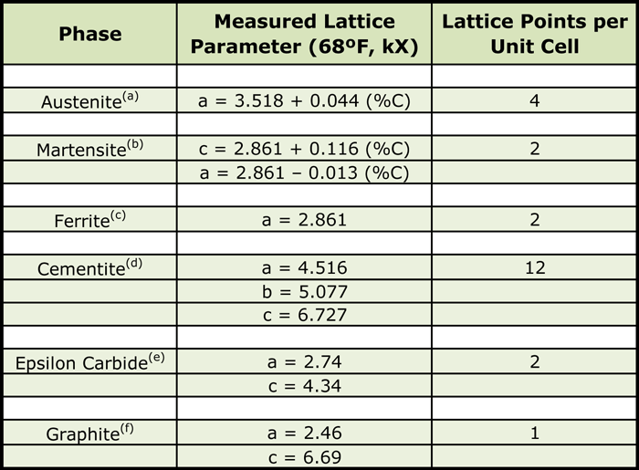
Dimensions of heat-treated parts undergo changes because of uneven temperature and structural phase transformations. On the basis of X-ray measurements of lattice parameters (Table 1) the specific volume (V) of the important phases and phase mixtures present in carbon steels can be calculated using the following equation:
(2) V = VC / (1.650nWP)
Where:
VC is the volume of the unit cell
n is the number of lattice points per unit cell
WP is the atomic weight per lattice point.
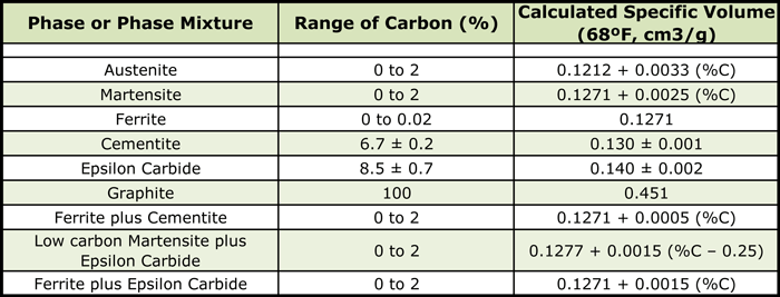
Calculated volumes of phases are given in (Table 2).

Notes:
(b) Body centered tetragonal
(c) Body centered cubic
(d) Orthorhombic
(e) Hexagonal close packed
(f) Hexagonal
The amount of retained austenite, as well as its carbon content, will affect the magnitude of the expansion associated with going from the annealed to the hardened state. The higher the carbon content of the austenite prior to quenching, the lower the Ms point, and therefore, the greater the amount of austenite retained after quenching to room temperature. Increasing the amount of retained austenite of a given carbon content tends to increase the contractive effect.
Cold treatment following hardening results in additional transformation of austenite to martensite. Dimensional changes will depend on the percentage of carbon in the martensite.
As an example (starting from the aggregate of ferrite and cementite in the annealed state and heating to austenitizing temperature and then quenching in oil to get martensite) one calculates the following:
The dimensional change from the annealed state to austenite is:
= – 0.0155 + 0.0074 (%C) inch/inch
Now, from austenite to martensite, the dimensional change is:
= 0.0155 – 0.0018 (%C) inch/inch
Therefore, the dimensional change from the annealed state to martensite is:
= – 0.0155 + 0.0074 – [0.0155 – 0.0018 (%C)]
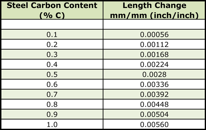
= 0.0056 (%C) inch/inch
The dimensional changes will, therefore, depend upon the percentage of carbon in martensite (and the percentage of retained austenite).

Final Thoughts
Whether through empirical trials or theoretical calculations, dimensional change is a given. Managing this change is the responsibility of both the manufacturer and the heat treater who must work together to achieve a level of change, which is manageable for both. The good news is that, today, control and repeatability of the process reduce the number of “surprises” one may encounter.
References
- McKenna, Patrick and Herring, Daniel H., Predicting Size Change from Heat Treatment, Production Machining, November 2010.
- Herring, Daniel H., Dimensional Changes in Hardening, White Paper, 2004.
- Böhler Uddeholm Data Sheet
- Latrobe Data Sheet.
Daniel H. Herring / Tel: (630) 834-3017) /E-mail: dherring@heat-treat-doctor.com
Dan Herring is president of THE HERRING GROUP Inc., which specializes in consulting services (heat treatment and metallurgy) and technical services (industrial education/training and process/equipment assistance. He is also a research associate professor at the Illinois Institute of Technology/Thermal Processing Technology Center.
