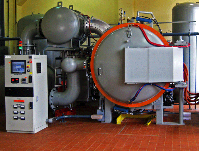
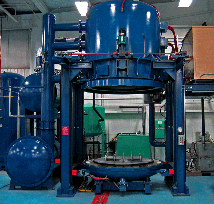
Vacuum furnaces come in all shapes and sizes but common to each is that they require some type of vacuum vessel (Fig. 1). Most vacuum vessels in the heat treating industry are cylindrical in shape and either horizontal or vertical in orientation (Fig. Nos. 2 – 3). In general, vacuum vessel designs are made as small as possible so long as they don’t hamper the process being run in the vessel. There are several obvious reasons for this including the cost of the vessel itself as well as the vacuum hardware involved. In addition pumping systems become larger and operating costs tend to be higher (e.g. more gas is required for quenching).
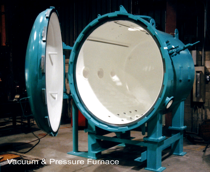
The design of a vacuum vessel may be very specific for the intended application but usually, all vessels have the following features in common:
- Basic design (i.e. structural integrity)
- Welds
- Surface finishes
- Flanges
- Seals
- Fasteners
- Feedthroughs
- Lubricants (e.g. vacuum grease)
- Mounting brackets
- Access (e.g. doors, ports)
- Testing
- Vacuum integrity (e.g. the absence of leaks)
Vacuum Vessel Design
Some of the basic engineering considerations include:
- Service Environment
- Physical (space) limitations
- Pressures and forces
- Temperature
- Application specifics
- Materials of construction
- Standards & codes
Designs for vacuum vessels involve two distinct aspects; one structural and one related to the process application. The basic structural design falls in the realm of mechanical engineering following established industry guidelines, an example of which is the ASME Boiler and Pressure Vessel Code, Section 8 Division 1 (Rules for Construction of Pressure Vessels) for vacuum furnaces utilizing high-pressure gas quenching (above 14.7 psig). The design must take into account both the external and internal forces acting on the vessel to prevent buckling (i.e. structural instability) and deal with overpressure issues, both major concerns from a strength of materials standpoint.
With regard to internal design, there are two further considerations, minimizing the residual gas content and providing appropriate penetration openings for the various components of the vacuum system (e.g. connections between vacuum pumps and the chamber and the connection between the vacuum gauges and the area where the pressure is to be measured). The materials of construction, welding/brazing/soldering techniques, and internal surfaces are chosen to minimize unwanted gas evolution. Joints, ports, gaskets and “O” ring grooves must be made so as to avoid trapped gases.
The most common materials used for the construction of vacuum vessels in the heat treatment industry are steel and stainless steel. In certain high vacuum applications, aluminum and glass are also used.
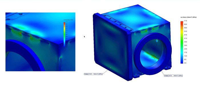
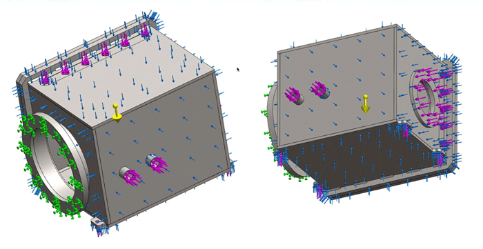
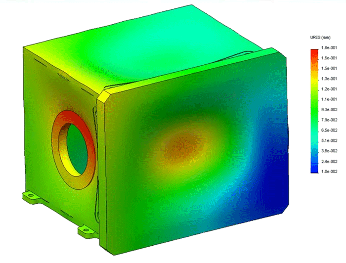
In the pre-design phases and when checking the final design, somewhat simple analytical methods are often used with or without the aid of structural analysis programs. Today’s advanced software permits quick analysis of the effects of various geometric parameters. These structural analysis packages, usually based on Finite-Element Analysis (FEA) methods, are used for the detailed design of vacuum vessels. Two main families of elements are typically used for these computations: the solid elements for machined parts and shell elements for the shell structure. Other uses include design elements such as material stress analysis (Fig. 4), weld stress (Fig. 5) and deformation (Fig. 6)
End User Considerations
When building or purchasing a vacuum vessel, be sure to ask the following questions:
- Will a standard chamber work for my application or is a custom design necessary? In a standard design, for example, the manufacturer predetermines the number and location of ports. In a custom design, flexibility and expandability are the most important considerations.
- Will I be running a conventional or special process? If the process is an established one, it is still important to draw upon the vessel manufacturer’s experience in the industry and knowledge of what has been incrementally improved or upgraded.
- For a special process function often comes ahead of form and there may need to be design trade-offs if issues such as equipment delivery are important. Attention must also be paid to ease of repair or replacement should the process not be optimized in the beginning causing damage to the vessel.
- Ask who can provide input on the design of the vessel to ensure that it will meet expectations. Resources can be both internal (process experts, maintenance personnel, controls or automation specialists, etc.) and external (original equipment manufacturers, component suppliers, colleagues in the same field).
- Will the chamber be stand-alone or part of a larger and possibly integrated system? Will the chamber be self-supporting? Will a crane or other device be needed to move heavy sections for service repairs? How will it be orientated (horizontal or vertical) and what are the space/access requirements (in use and for service – which components need access and how much, including pumps, valves, controls, etc.) The footprint must allow for the operational needs of the system as well as disassembly and maintenance.
- How automated will the system need to be and what level of training (operator, supervisor, maintenance, engineering) will be needed?
- How will the chamber be loaded and what interlocks are involved?
- Where in the chamber will the process be performed? Will there be a need for internal workload or component movement.?
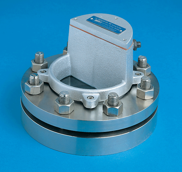
- What services need to be provided (electrical, heating & cooling requirements, gases)? Are viewports provided and if so what type or vision do they provide. Are they lighted (Fig. 7)?
- What type of components will be attached to the vacuum vessel and what type of support structure is needed? What types of safety components are needed/installed on the system and what type of access/service is required? What service frequency is required (e.g. pressure relief valves)? What type of gases are involved and what type or safety issues do these entail? Are there hazardous materials in use? What voltage and current levels are involved and what is the possibility that they may be transferred to the vessel (this often occurs when the insulation and internal components become conductive due to carbon pickup, etc.)? Is the vessel a confined entry space?
Vacuum Vessels Specifications
Some OEM’s fabricate their own vacuum vessels; some purchase them from third party suppliers. Understand where your vacuum vessel is coming from and insist on the right to inspect the vessel at any time during its manufacture. It is important to specify or understand the material choice and certification pressures. Also review the bill of materials, dimensions, fabrication methods (and notes), cleaning requirements, acceptance/performance testing (and verification), packaging and shipment details, attachment of component parts and plans for putting the chamber in service.
Materials of Construction
Materials used in vacuum furnaces must be compatible with the process as well as the ultimate vacuum level requirement. They must be capable of being easily fabricated with appropriate strength and must be available.
The chamber must be designed for integrity, weight, durability and have an acceptable surface finish (e.g. sand or bead blasting followed by epoxy coatings on the inside of steel vessels to reduce outgassing). Some chambers are electropolished. Seals might be metals or elastomers but must be designed for the expected service temperatures and pressures. Lubricants should be capable of vacuum service.
Leaks
Vacuum vessel leaks (virtual or real) can come in the form of outgassing, diffusion, and permeation and originate from sources such as “O” ring grooves, screw threads and welds. Vacuum vessels must be sound and tested for leak rate, rate of rise and in some cases shell thickness/integrity by ultrasonic or other acoustic methods. The integrity of the chamber should be checked at the manufacturer as well as after final installation in the field.
Construction Methods
Most vacuum vessels fabricated from steel or stainless steel plates are joined together by welding. Small chambers may be castings or even machined. Dimensional tolerances should be appropriate for the application with respect to linear dimensions, port placement, and alignment.
Other Design Hints
A variety of professional assistance is available, such as design classes from the American Vacuum Society (AVS), various manufacturers and design/simulation software houses. Remember that the vacuum vessel is only one component in an entire system so endeavor to understand the interaction between the chamber and the process. Don’t use unreasonable tolerances. Don’t over specify materials or surface finishes.
Vessel Replacement
Replacement of a pressure vessel is an atypical occurrence in the heat treat industry. Nevertheless, replacing a pressure vessel nearing the end of its useful life is not a simple undertaking – especially if that pressure vessel is decades old. Changes to specifications, technology innovations, and modifications to the original design specification over the lifetime of the older vessel all need to be taken into consideration in replacement planning. Factors to consider involve decommissioning the old vessel, disassembly/inspection/refurbishment/upgrade and/or replacement of components as well as the design and engineering of the new vessel to ensure safety, timeliness, and cost. When working with the pressure vessel manufacturer it is important to communicate all of the engineering information and performance/application requirements to the designer.
Replacement of a pressure vessel also opens a window of opportunity to take advantage of new innovations in design or new design and construction methods that may improve your production efficiency. Or, you may simply wish to use this opportunity to modify the original design spec to accommodate for changes in your business, adjust for new applications or again, to achieve unrealized efficiencies.
Finally, depending on the age of the pressure vessel, there may be changes to regulatory codes such as ASME specifications that must be accommodated within the new vessel’s design specification. For example, ASME now requires that the design specifications take into consideration repetitive or “cyclic” loading, which can result in fatigue damage. It is important that your supplier be conversant in the current ASME specifications and that the replacement vessel be designed in accordance with code.
Final Thoughts
To ensure that good vacuum design principles are being followed, share application information and needs with your vendor of choice. Use the vendor’s knowledge and expertise to supplement your own knowledge. Finally, keep the vendor in the loop after the chamber has been put into service.
References
- Herring, Daniel H., Vacuum Heat Treatment, BNP Custom Media II, 2012.
- Hablanian, Marsbed H., High-Vacuum Technology: A Practical Guide, Marcel Dekker Inc., 1990.
- Garton, David., Michael Mann and David Button, The Development of Vacuum Engineering Guidelines at ANSTO, SNEAP 2012.
- Peacock, Niel, Key Elements of Vacuum Chamber Design: Will They All Fit on a Napkin or Envelope?, MKS Instruments, HPS Products, September 2010.
- Hauviller, C., Design Rules for Vacuum Chambers, Spain, 2006.
