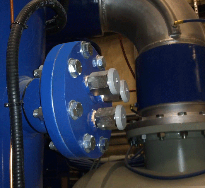
One of the most critical components on any vacuum furnace is the pressure relief valve. While its function is clear, the fact that it needs to be inspected – and tested is either not well understood or simply ignored. Normally positioned atop a vacuum furnace (Fig. 1) it is in an area that is not always conducive to maintenance, and complicated in many instances by the fact that only the manufacturer can service them.

What is a Pressure Relief Valve?
A pressure relief valve is a safety device designed to protect a vacuum furnace from over-pressurization. An overpressure event refers to any condition that would cause the pressure to increase beyond the specified design pressure (the so-called maximum allowable working pressure or MAWP). The pressure relief valve is an integral part of the safety system provided on most vacuum furnaces. Vacuum vessels, including evacuated chambers and associated piping, pose a potential hazard to personnel and the equipment itself from collapse, rupture, or implosion.
Do I Need a Pressure Relief Valve?
Pressure relief valves are mandatory on any vacuum furnace system using pressurized gas and operating (including gas quenching operations) over 103.4 Pa (15 psig). In addition, vacuum vessels and ancillary equipment (e.g., accumulator or surge tanks, gas storage systems including dewars, air compressors,) must be designed to ensure that allowable stresses are not exceeded and to ensure that the vessel is stable (resistant to buckling). Since pressure relief valves are safety devices, there are numerous international codes and standards written to control their design and application.
Codes and Standards
In most countries, manufacturers are legally required to protect pressure vessels and other equipment by installing relief valves. In most countries, equipment design codes are provided by organizations such as ASME (e.g., BPVC), ISO (e.g., ISO 4126), European Standard (e.g. EN-764-7) and API recommended practices to name a few. These standards are mandatory and their design standards must be complied with for all relief valves.
The ASME Boiler and Pressure Vessel Code (BPVC) is unique in the United States and Canada, having been adopted by the majority of state and provincial legislatures and mandated by law. Compliance with this code is mandatory for vessels with an external pressure not exceeding 103.4 Pa (15 psig) under Section VIII Paragraph U-1(c)(2)(h), but the design rules may be applied to all vacuum furnaces. Under Section VIII, Paragraph UG-28(f), such vessels may be code stamped. Also, any repairs to or modifications of the pressure vessel require recertification.
The most widely used voluntary standards for pressure vessels (in the United States) are published by the American Petroleum Institute (API). These Standards provide recommended practices for pressure relief valve construction, sizing, installation and maintenance and are a good source for general knowledge.
Design Considerations
There are a number of different types of pressure relief devices (e.g. pressure and temperature safety relief valves, steam or vapor relief valves, liquid safety valves, safety relief valves, rupture discs), the choice of which most often depends on the application use.
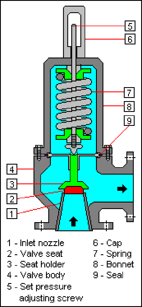
Most vacuum furnace pressure relief valves are spring-loaded devices (Fig. 2). Essentially, the valve consists of a housing with an inlet nozzle mounted on the vacuum furnace (or other pressurized components), a disc held against the nozzle to prevent flow under normal system operating conditions, a spring to hold the disc closed, and a body/bonnet to contain the operating elements. The spring load is adjustable to vary the pressure at which the valve will open.

In high-pressure gas systems, it is recommended that the outlet of the relief valve is unrestricted, discharging into the room. However, there are exceptions such as furnaces running combustible gases (e.g., hydrogen partial pressure or process gas or acetylene for low-pressure vacuum carburizing). In systems where the outlet is connected to piping, the opening of a relief valve will give a pressure build-up in the piping system downstream of the relief valve. This often means that the relief valve will not re-seat once the set pressure is reached. For these systems so-called “differential” relief valves are often used. This means that the pressure is only working on an area that is much smaller than the opening area of the valve. If the valve is opened the pressure has to decrease enormously before the valve closes and the outlet pressure of the valve can easily keep the valve open. Another consideration is that if other relief valves are connected to the outlet pipe system, they may open as the pressure in the exhaust pipe system increases. This may cause undesired operation.
Another important consideration in the design of a pressure relief valve is the ability to maintain a tight seal (leaky valve will often “hiss” as pressurized gas escapes). Leakage is common on valves that have been triggered by a pressure event. Since pressure relief valves are required to remain on systems for many, many years under a wide variety of furnace pressure and temperature conditions, a small leakage will often result in progressive damage to the valve seating surfaces. Extreme leakage can even result in the premature opening of the valve and destroy the ability to maintain pressure within the vacuum system. Allowable seat leakage limits for pressure relief valves are many orders of magnitude more stringent than required for other types of valves. These extremes of tightness are achieved by close control of part alignment, optically flat seating surfaces, and careful selection of materials for each application.
Maintenance Practices
A well thought out and strictly adhered to maintenance schedule based on the manufacturer’s instructions must be carried out in the field to ensure the valve will operate properly when called on to do so. Inspecting the integrity of the value (and in particular that it is leak-tight) is mandatory. Most pressure relief valves on vacuum furnace systems are so-called “one and done” discharge devices and as such are not cycled or cycle checked. If a pressure relief valve does discharge, in most cases it cannot be reset in the field (check the valves operating instructions!) and needs to be returned to the factory for inspection and testing. Pressure relief valves should also be factory tested and calibrated annually or on a time schedule recommended by the manufacturer. As such, it is always a good idea to have a spare valve of the proper size on hand.
Most manufacturers recommend that the system operating pressures not exceed 90% of set pressure to achieve and maintain proper seat tightness integrity. Since pressure relief valves are normally supplied by the OEM (original equipment manufacturer) it is important to understand the design parameters and service restrictions that have been selected by them.
Once a condition occurs that causes the pressure in a system or vessel to increase to a dangerous level, the pressure relief valve may be the only device remaining to prevent a catastrophic failure. Since reliability is directly related to the complexity of the device, it is important that the design of the pressure relief valve be as simple as possible.
The pressure relief valve must open at a predetermined set pressure, flow a rated capacity at a specified overpressure, and close when the system pressure has returned to a safe level. Pressure relief valves must be designed with materials compatible with the gas (or liquid in some cases), from simple nitrogen or argon to potentially more corrosive fluids. They must also be designed to operate in a consistently smooth and stable manner on a variety of fluids and fluid phases.
Tips for Pressure Relief Valve Inspection
Detailed general testing and operational inspection guidelines can be found in the National Board Inspection Code (c.f. Part 2 2.5.4 and 2.5.7). Recommended inspection and test frequencies can also be found in the National Board Inspection Code (c.f. Part 2 2.5.8). Additional information to aid inspections of pressure relief devices, including installation requirements, can be found in the following publications and sources:
- National Board Inspection Code
- ASME Section I, IV, VI, VII, VIII (Divisions 1, 2 and 3), X, CSD-1
- Manufacturer’s Installation, Operation, and Maintenance Documentation
- Local Laws, Rules, and Directives
During the inspection of a vacuum furnace, the individuals involved should be familiar with the pressure relief device installed on the furnace and its associated equipment. Some of the things to look for in an inspection are the following:
- Compare the device nameplate set pressure with the maximum allowable working pressure and ensure the device set pressure does not exceed the valve rating. A device with a set pressure less than MAWP is acceptable. If multiple devices are used, at least one must have a set pressure equal to or less than the MAWP. The ASME Code should be reviewed for other conditions relating to the use of multiple devices.
- Ensure the device still has the device manufacturer’s seals intact. These seals can be in the form of wire through a drilled hole with a soft metal button, such as lead, crimped on the wire, or removable parts may be stake punched or crimped to inhibit accidental movement. Any evidence of the seal mechanism being broken or destroyed could indicate tampering. If this is found, replacement of the device or repair by a qualified organization is recommended.
- If there is an inspection tag on the device, make sure that it is current, signed and dated where appropriate. Do not assume the device has been inspected or tested unless it has such a tag.
- Verify the discharge of the device is piped to a safe point of discharge.
- Some devices have test levers. Lifting the test lever of a spring-loaded device may not be practical in all cases when inspecting pressure vessels. Familiarize yourself with the manufacturer’s instructions before attempting to lift the lever. Some must be lifted with no pressure present, others must have at least 75% of the device set pressure under the device disk prior to lifting the test lever. If the device is stuck in a closed position, the equipment should be immediately removed from service and the equipment not operated until such time the device can be replaced or repaired.
Summary
Pressure relief valves are one of the most oft times overlooked safety devices installed on vacuum furnaces. The reader is challenged to go out to their equipment, find and read the manufacturer’s recommendations as to the operation, inspection, maintenance, and testing of these devices. You will be glad you did.
References
1. Wikipedia (en.wikipedia.org).
