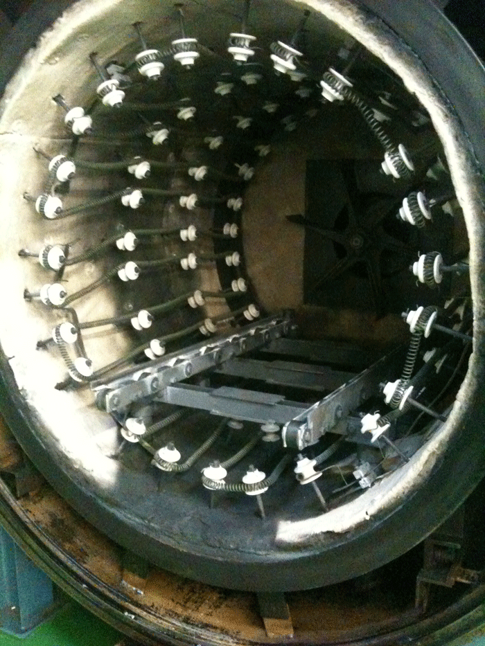
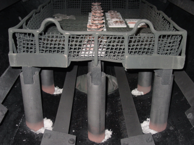
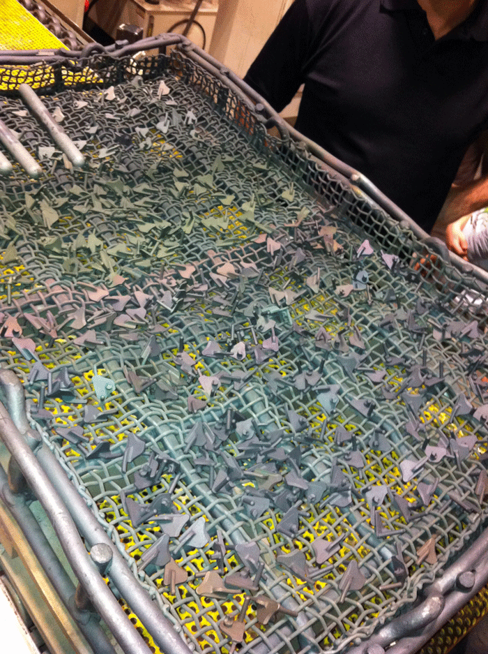
When operating vacuum furnaces, situations may arise in which the hot zone and/or cold walls may become contaminated (Fig. Nos. 1 – 2). This can occur from a variety of sources: air leaks, outgassing from residues left on the parts as a result of the manufacturing or cleaning processes, vaporization of sensitive materials (e.g., chromium-bearing materials), process induced contaminations such as carbon in the form of soot or tar, fluxes from brazing pastes, excess braze alloy as well as many other sources. Often times the work being processed is also affected (Fig. 3). The question becomes, how do we attempt to clean up our contaminated vacuum furnaces?
Clean-Up Procedures
The following tests and cleanup procedures are recommended on any vacuum furnace.
1. Leak Test: This test should be performed as part of routine operation and maintenance of equipment and typically consists of isolating the heating chamber (i.e., no pumping on the chamber) for a period of one (1) hour and measuring the increase (if any) in vacuum level. For single chamber vacuum furnaces, 10 – 20 microns per hour is considered an acceptable leak rate for general heat treatment (Note: specific materials, parts and/or processes may require a significantly lower leak rate). The vacuum level should be recorded before and after the test. Detailed procedures can be found in Reference 1.
2. Baseline Test: Running test pieces or production parts in other vacuum furnaces for comparative purposes (e.g., surface appearance) is a simple method of determining if a cleanup (aka burnout) cycle is required (and subsequently how effective the cleanup cycle was after it was run).
a. Materials such as 300 series stainless steel can be used, and if necessary, more sensitive materials (e.g., stainless steels containing titanium additions (e.g. 321SS), Inconel or other exotic materials).
b. Clean test pieces with alcohol. Water rinse and alcohol clean again, then hot air dry. Note: Be extremely careful in handling samples so as not to introduce contaminants, especially when trying to ascertain surface appearance.
c. Cycle – 1040ºC (1900ºF), 1 hour, vacuum cool to 50ºC (120ºF)
d. Inspect under natural (not shop or office) light, photograph and preserve samples in sealed bags purged with nitrogen.
3. Cleanup (aka Burnout) Cycle:
a. Inspect and photograph the furnace interior.
b. Clean as much foreign debris out of the furnace as possible. Caution: Be aware of the impact of any (cleaning) chemicals introduced into the system.
c. Check the maximum operating temperature of the unit and stay a minimum of 25ºC (50ºF) below this temperature during any burnout cycle.
d. A generic burnout procedure for a single chamber vacuum furnace with a maximum operating temperature of 1340ºC (2450ºF) might be to heat to 1315ºC (2400ºF), soak for 6 – 8 hours (once set point has been reached), then vacuum cool (no backfill) to 50ºC (120ºF). Inspect and photograph the interior.
4. Assessment:
a. If an improvement in appearance has been achieved a decision needs to be made if a second cleanup cycle should be performed. Note: In most cases, there is only marginal improvement after two cleanup cycles have been run.
b. If no improvement was observed, consider performing a hydrogen cleanup (burnout) cycle (see below).
Hot Zone Maintenance
A hot zone burnout (aka bake-out) cycle should be run every 200 hours or when deemed necessary by degradation in equipment performance or changes to the surface appearance or properties of the component parts being run.
Before performing this operation one should check the condition of the hot zone. In particular, check the insulation (looking for damage or deterioration), check that electrical connections are tight (e.g. heating elements, power feedthrus), inspect the heating elements for wear and/or oxidation (e.g. thinning or a “sugar cube” appearance – indicating attack by oxygen), measure resistance to ground, and check that thermocouples and controls are functioning properly.
In the event that the contamination is too extensive to overcome by a burnout cycle, it may be necessary to perform a hydrogen burnout (aka bake out) cycle. If this path is chosen, extreme care must be exercised prior to and during the introduction of hydrogen into the vacuum furnace. First, the original equipment manufacturer should be consulted as to the best procedure to use; it is good practice to have the manufacturer’s service personnel on-site to assist with the procedure. Second, the furnace must not be left unattended at any time. Third, emergency nitrogen or argon backfill should be initiated at the first indication of a problem (for example, a loss of power during the run). Finally, all necessary safety equipment and procedures should be in place and personnel properly trained on the procedure they are about to use (see below).
Generic Hydrogen Burnout Cycle for a Single Chamber Vacuum Furnace
The following is a generic hydrogen burnout cycle for a single chamber vacuum furnace with a maximum operating temperature of 1340ºC (2450ºF).
1. Pump down to high vacuum (10-5 Torr)
2. Heat in high vacuum at 8ºC/min (15ºF/min) to 1175ºC (2150ºF)
3. Heat in high vacuum at 3ºC/min (5ºF/min) to 1315ºC (2400ºF)
4. Introduce partial pressure of hydrogen (Note: The blower should be running)
a. 5 – 10 Torr absolute pressure as measured on a mechanical gauge (not a thermocouple gauge)
b. Flow rate: 4.25 m3/h (150 SCFH) hydrogen
5. Soak for 1 ½ hours
6. Pump down to high vacuum (10-5 Torr)
7. Re-introduce partial pressure hydrogen (as above)
8. Soak for 1 ½ hours
9. Pump down to high vacuum (10-5 Torr)
10. Vacuum cool
11. Repeat steps (1) thru (10) – do not open door between runs
12. Inspect and photograph the hot zone
13. Repeat as necessary if hot zone looks improved
Hydrogen Safety
The following is advice gathered from a number of industry experts on what you should watch out for and what precautions are necessary when using a hydrogen atmosphere.
IMPORTANT NOTE: ADHERENCE TO NFPA 86 AND OSHA GUIDELINES IS MANDATORY; THESE ARE ONLY SUGGESTIONS AND DO NOT NECESSARILY CONSTITUTE NFPA COMPLIANCE:
1. The vacuum furnace leak rate must be 10 microns per hour or less prior to any processing with hydrogen.
2. The pressure relief valve and/or chamber release valve must be vented outdoors via a hard pipe on an upward angle to ensure no trapped hydrogen gas. Use of an inert gas added to this venting line for purging capabilities will help
ensure no trapped hydrogen gas.
3. If any amount of gas venting from the furnace is minimal, it is possible to burn the gas at the exit. Be sure to use a check valve.
4. Ensure there are no leaks in the hydrogen supply lines. A vacuum should be pulled on the hydrogen supply lines to check for leaks. Bubble checking of all fittings while under pressure should be part of routine maintenance.
5. Before opening the furnace door, pump down to less than 100 microns, backfill with an inert gas. It would be a good idea to perform this operation one (1) additional time to dilute any hydrogen gas trapped in the pumping exhaust
system.
6. Institute a good preventative maintenance program/schedule that includes inspecting furnace integrity. Items should include such things as inspection of O-rings (not only if they are dirty but also that they are not flat),
disassembly of solenoid valves to clean their surfaces and components and oil changes on pumps as well as the condition of the belts so to avoid pump failure.
7. Intrinsically safe and redundant control systems to ensure operator mistakes are minimized. Such as venting, door opening, air releasing . . .
8. Compliance with NFPA 86 (latest edition) is mandatory.
9. Provide an inert gas flow, typically 2.83 m3/h – 4.24 m3/h (100 cfh – 150 cfh) to the mechanical pump plenum at all times when hydrogen is flowing. Install an inert gas line to the pumping exhaust line to purge hydrogen gas out
at any time.
10. Have a manual safety shutoff valve added to the hydrogen supply line that is easily accessible and prominently labeled.
11. All hydrogen supply lines shall be metal, not flexible plastic. No cast iron components are allowed.
12. Before the hydrogen circuit is enabled, the use of an interlock is mandatory, which will not allow the addition of hydrogen until the furnace has been evacuated to below 0.13 mbar (100 microns).
13. Hydrogen supply lines shall be equipped with high and low-pressure switches to prevent operation above and below specified pressure ranges.
14. Components that use hydrogen shall be designed and approved for “hydrogen use”.
15. Consider the use of a flow-limiting valve on the hydrogen supply line to limit the maximum allowable flow.
16. Mechanical roughing pumps on all furnaces should have “run monitors” installed and interlocked to ensure that the pump itself (not just the pump motor) is operating.
17. Ballast valves on all mechanical roughing pumps should be plugged to prevent the accidental introduction of air into the pump while hydrogen is being used.
18. Change all vacuum line air-release valves to normally open style. Pipe those valves to an argon supply equipped with a low-pressure regulator (with a pressure gauge) set no higher than 6900 Pa (1 PSIG).
19. Remove sight glasses from the furnace.
20. Always have an operator nearby when operating with a hydrogen atmosphere.
21. Provide five (5) times the volume of inert gas standing by at all times ready to purge the furnace of hydrogen in an emergency or a power failure situation.
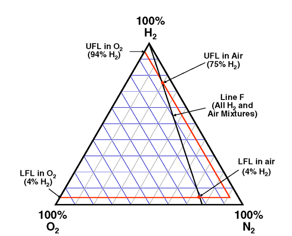
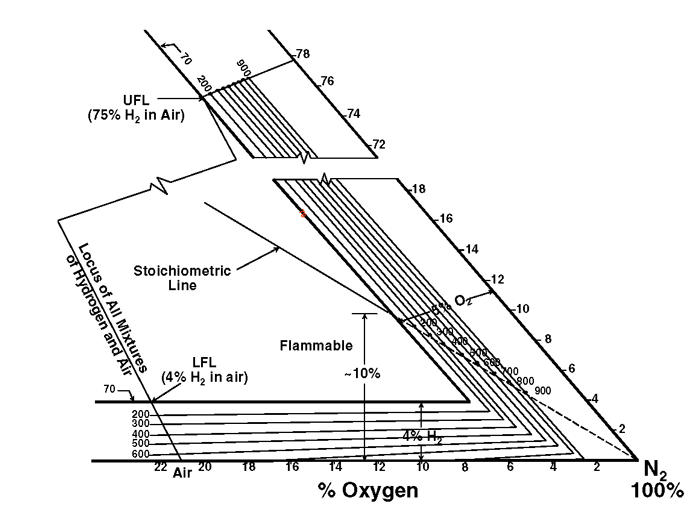
A full tertiary diagram (Fig. 4) for hydrogen, oxygen, and nitrogen includes the flammability envelope for ambient conditions. Mixtures inside the envelope are flammable. Temperature corrections (Fig. 5) have been determined, assuming oxygen is the contaminant.
Additional Notes/Cautions
Here are some additional notes of interest as they relate to common problems experienced during clean up cycles.
1. There is often a gray appearance on metallic hot zone heat shields (a typical combination being 2 molybdenum shields + 3 stainless steel shields) indicating there are oxides of molybdenum and chromium present on the shields. The form of molybdenum oxide is most likely molybdenum trioxide (MoO3), the most difficult to clean up (for example, a 1315ºC (2400ºF) hydrogen cleanup cycle being marginal to reduce MoO3). In many cases, however, a hydrogen burnout cycle will result in considerable improvement of these surfaces.
2. Backstreaming issues may have been the result of one or more of the following conditions:
a. Not properly valving off the diffusion pump in operation. The unit should be pumped down to 50 microns before opening the valve to the diffusion pump (never open the valve at a pressure higher than 150 microns).
b. When initiating the cooling cycle, make certain the high vacuum valve is closed. A good procedure would be to introduce a 5-second delay before the onset of cooling to ensure the valve has closed.
c. The holding pump may not be functioning properly. The foreline pressure should be 100 – 150 microns (Varian recommends no higher than 750 microns, although the industry considers 1 micron the maximum foreline pressure). This value should be measured by a thermocouple gauge installed in the foreline piping.
d. The type of oil in the diffusion pump makes a significant difference. A Dow Type 704 fluid is recommended (it allows for a deeper vacuum than say Dow Type 702 and is less prone to issues should air infiltrate into the system).
e. The foreline valve may not be operating properly – this is often the result of jamming of the foreline baffles, which close off the opening.
f. The jets (i.e., nozzles) in the diffusion pump may be partially blocked due to residue buildup.
3. A common source of air infiltration is the front door “O” ring, which may be flat or dirty. Under vacuum, the “O” ring may be performing properly (hence the ability to achieve 10-5 or 10-6 Torr vacuum levels). However, when the
backfill starts the “O” ring may be opening up, allowing air to enter the system.
4. An operating vacuum level in the 1.5 – 2 x10⁻⁵ Torr calculates to a leak rate of (approximately) 5 microns/hour.
In Summary
Cleanup cycles are not only a good practice for routine and preventative maintenance but for the long-term condition of the vacuum system. In some rare instances, however, such as the processing of superalloys or exotic materials, the contamination may be so severe that the replacement of the hot zone is the only viable option.
References
1. Herring, Daniel H., Vacuum Heat Treatment, BNP Media Group, 2012.
2. Dwyer Jr., John, James G. Hansel, and Tom Philips, “Temperature Influence on the Flammability Limits of Heat Treating Atmospheres”, Air Products and Chemicals, Inc., 2003.
3. Jones, Trevor “Explosive Nature of Hydrogen in Partial Pressure Vacuum”, Heat Treating Progress, February 2009.
