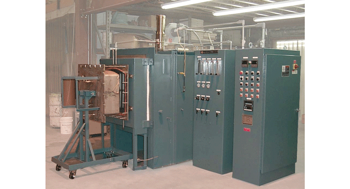
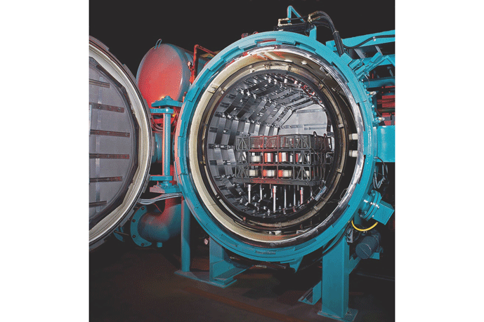
Vacuum furnaces can be either hot wall (Fig. 1) or cold wall (Fig. 2) designs. There are notable differences between the two, and each has specific advantages and limitations. In this and our next article, we will examine these differences and describe which applications are best suited for each.
Hot Wall Designs
Early in the history of vacuum furnaces, hot wall designs were the only ones available. These furnaces, just as the ones today, utilize a retort (aka muffle) into which the load is placed. The retort is then sealed. A pump evacuates the retort and the process runs either under vacuum or at a specific (negative or positive) pressure once the initial vacuum level is reached.
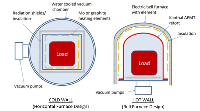
The advantages of using a retort include the fact that the furnace surrounding the retort can be gas-fired or electrically heated and that the retort can be rapidly pumped down. Hot wall designs are generally less expensive to manufacture than their cold wall counterparts. In addition, since the volume inside the retort is relatively small, the pumps are smaller and it takes less time to reach the required vacuum level for the process than a cold wall furnace of comparable size (Fig. 3).
Notes:
- The blue shaded area represents the volume required to be pumped down.
- The figure on the left illustrates a rectangular hot zone. Cylindrical designs are more common today.
In hot wall designs, the heating source is located outside the retort, but within the furnace itself. By contrast, cold wall designs have their heating source within the furnace hot zone (Fig. 4). The defining characteristic of the hot wall design and its major limitation is the fact that a retort must be used.
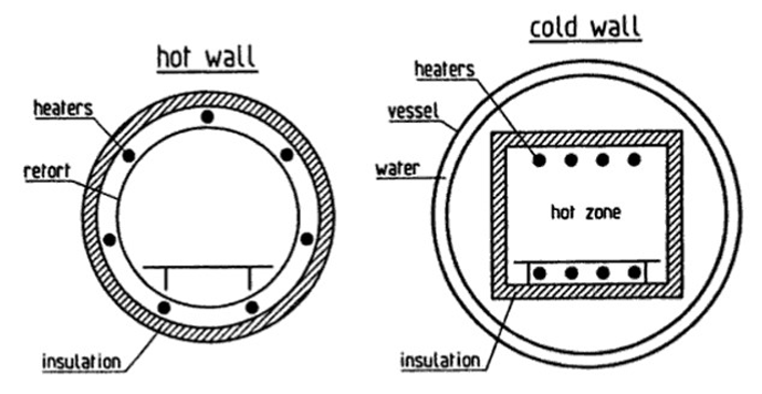
In normal operation, a vacuum is created inside the retort prior to heating. Once a given vacuum level is achieved, the process can continue to run under vacuum, or at a partial or positive pressure if an inert (or combustible) gas is introduced. Fans are often supplied inside the retort in order to circulate the atmosphere. In order to heat the load, the heaters must first externally heat the retort and then the retort conducts or radiates the heat to the load within.
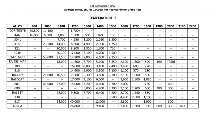
If the retort is subjected to atmospheric pressure on the outside and a given vacuum level on the inside, the retort construction must be such that it prevents the retort from collapsing. Since all materials are, to varying degrees, susceptible to reduced strength at elevated temperature (Fig. 5) and to fatigue after repeated cycling, the materials of construction and design of the retort must take these factors into consideration. Thus, hot wall units inherently have a lower maximum operating temperature than cold wall designs. Hot wall designs are typically limited to 1100°C (2000°F) maximum. In addition, retorts can also be made from ceramic or quartz, which have higher maximum temperatures but can be susceptible to thermal shock on heating and cooling. These materials offer the advantage of less contamination of the process vacuum and are used primarily in high purity applications such as those in the semiconductor industry.
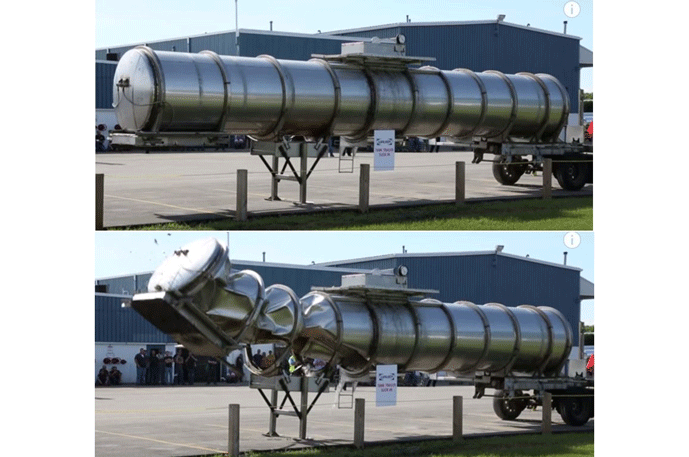
Retort construction can be D-shaped, cylindrical, or rectangular. Retorts are also often corrugated to provide additional strength. Since atmospheric pressure is slightly above 10,000 kg/m2 (14.7 lbs./in2), a retort under vacuum experiences tens of thousands of kilograms of force trying to collapse it. This compressing force can be demonstrated by pumping the air out of a drum or steel tank and noting how suddenly and dramatically the tank collapses (Fig 6). As a result, all retorts need to be adequately reinforced.
Forced Cooling in Hot Wall Vacuum Furnaces
Hot wall retort vacuum furnaces often need to be force cooled in order to achieve a reasonable process cycle time. This can be done by either removing the retort from the furnace or circulating cooling air around the exterior of the retort.
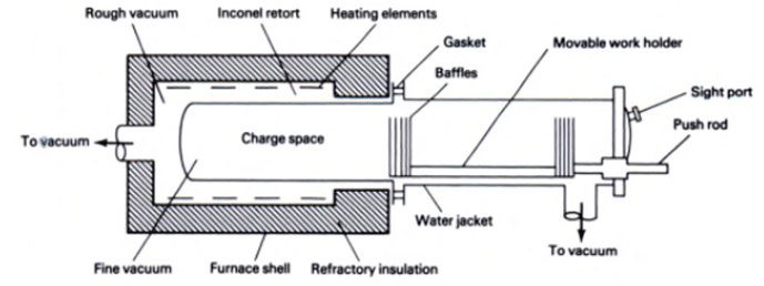
Another method of cooling involves an extended retort design (Fig. 7). The retort is lengthened so it extends outside the heating chamber, and the exterior section is wrapped with a water jacket for cooling. A movable grid carrying the load is transferred in and out of the furnace via a push rod passing through a seal at the end of the retort. When heating is complete the grid holding the tray of parts is pulled out of the heated portion of the retort and is positioned into the water-cooled section of the retort. The load stays under vacuum the entire time.
Another way to cool the load in a hot wall vacuum furnace is to inject ambient air into the furnace, on the outside of the retort (Fig. 8). The furnace being illustrated is designed to draw a vacuum, followed by backfill with an inert gas.
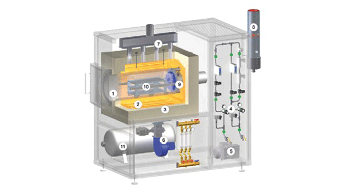
This isometric cutaway illustrates the following furnace features:
- Retort (Item 1)
- Heating elements (Item 2)
- Furnace insulation (Item 3)
- Gas management system (Item 4)
- Vacuum pump (Item 5)
- Cooling fan (Item 6)
- Exit path of the cooling air (Item 7).
- Gas exhaust (Item 8)
- Gas circulation fan for inert atmosphere circulation after backfilling (Item 9)
- Load (Item 10)
- Emergency purge tank (Item 11)
Process Applications
Hot wall vacuum furnaces are used for various processes including tempering, brazing, coating, curing, removal of impurities and case hardening (nitriding, nitrocarburizing, sulfonitriding).
References
- Kanthal (www.kanthal.com)
- Steel Heat Treatment Handbook, George E. Totten and Maurice A.H. Howes (Eds.), Marcel Dekker, Inc., 1997.
- Alloy Engineering (www.alloyengineering.com)
- Wabash National Corporation (www.wabashnational.com)
- Vacuum Technology: Practical Heat Treating and Brazing, Roger Fabian (Ed.), ASM International, 1993.
- Nabertherm (www.nabertherm.com)
- Directindustry.com
