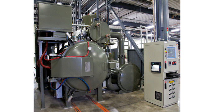
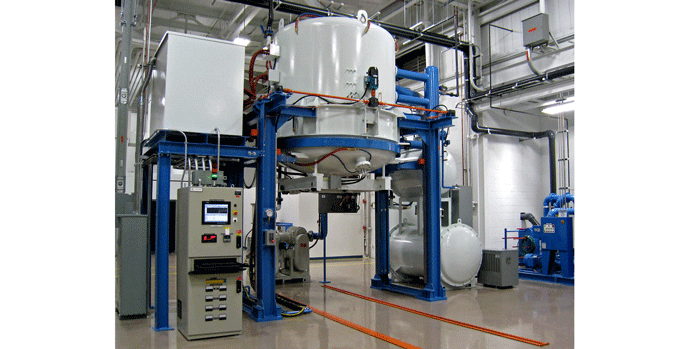
Cold wall vacuum furnaces dominate the vacuum furnace industry and are available in a variety of sizes and workload configurations (Fig. 1). In comparison to hot wall furnace designs in which the process is run inside a vacuum tight retort, the cold wall design runs the process inside a sealed vacuum vessel. As such, the furnace shell must not only be suitable for vacuum service but for operation at positive pressure.
Figure 1 | (a) Typical horizontal vacuum furnace (b) Typical vertical vacuum furnace
Historical Perspective
Before 1960, metallurgical heat-treatment processes in vacuum equipment were limited to specialized applications and relatively simple processes such as the annealing of copper wire. The introduction of industrial cold-wall furnaces increased the number of applications considerably because of the possibility to quench the charge by forced gas circulation (at pressures slightly below atmospheric). By the early 1970’s, cold-wall furnaces with oil quenching capability were introduced and by the mid-1980’s high-pressure gas quenching designs became available. Since the 1980’s the quench pressures have steadily advanced, from sub-atmospheric to as high as 25 bar, with 5 and 6 bar, 10 bar, and 20 bar dominating the industry.
Today, a wide variety of standard and custom heat-treatment processes can be carried out in vacuum furnaces including annealing, normalizing, stress relief, tempering, brazing, sintering and all forms of hardening operations. In addition, the proper control of the furnace atmosphere makes vacuum techniques suitable for such thermochemical treatments as carburizing/carbonitriding and nitrocarburizing.
Cold wall furnaces offer many advantages some of which include:
- Higher maximum temperatures than hot wall designs
- Faster load heating
- Greater control of temperature uniformity
- Lower heat losses to the surroundings
Design Features
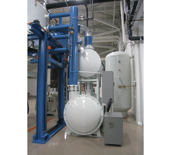
In cold wall designs, a hot zone (Fig. 2) consists of what is commonly referred to as a heat “cage” of either steel or stainless steel onto which both the insulation and heaters are attached. The hot zone is physically separated from the furnace vessel by what is known in the industry as an “air gap”. The insulation, which most often is either all graphite (Fig. 3), all metal (Fig. 4) or a combination of these materials, is physically attached to the heating cage. The heating source itself is located inside the insulation so that the load is directly exposed to the radiant energy produced by either electric elements (Fig. 5) or, less commonly, by radiant tubes. The door of the hot zone can contain an optional convection heating fan to help reduce cycle time for heavy loads. Gas quenching utilizes a circulating fan or blower and heat exchanger assembly for rapid cooling (Fig. 6). Oil quenching requires the load to be transferred to a separate chamber for immersion in special vacuum quench oil.
Cold wall furnaces commonly operate at temperatures up to 1315°C (2400°F), with standard designs available up to 1650ºC (3000ºF) and specialized furnace designs capable of up to 3000°C (5432°F).
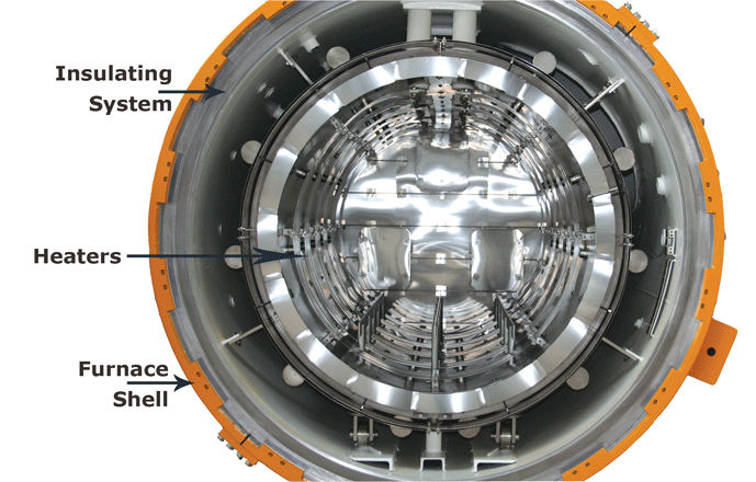
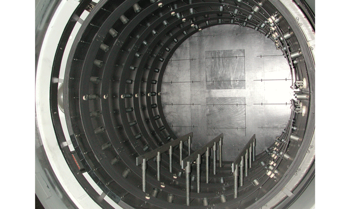
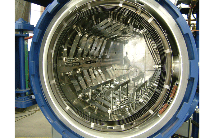
Figure 5 | Typical external heat exchanger and blower style quench system arrangement (a) schematic representation and (b) physical hardware 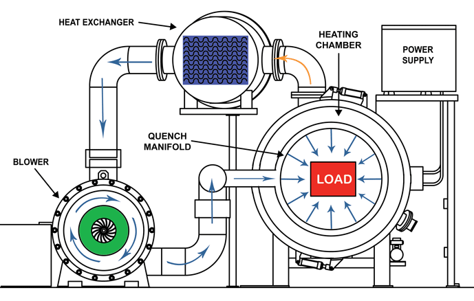
(a) Schematic representation
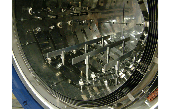
The fact that the load is exposed directly to the heat source allows for fast, energy efficient heating of the workload, unlike the hot wall design where the heat has to conduct through a retort. The technology that makes the cold wall vacuum furnace possible is water cooling of the furnace shell. This allows the shell to maintain its full structural integrity while the furnace is operating at elevated process temperatures and therefore permits significantly higher maximum operating temperatures than the hot wall design, where the retort is susceptible to failure since it simultaneously experiences both high temperature and full process vacuum or pressure.
In the cold wall design, the vacuum vessel (i.e. the furnace shell) must be much larger than the hot wall retort, to contain the workload, heaters, and insulating system. Since it has a larger interior surface area experiencing the vacuum, it must, therefore, resist a larger total atmospheric crushing force. Since the shell is held near factory ambient temperature in the cold wall design, it does not weaken due to elevated temperature during operation. It is critical, therefore, that the furnace walls be kept cool at all times to avoid structural failure.
Cold Wall Jacket Cooling Systems
Cold wall furnaces typically use a 25 – 30 mm (1 – 1 ¼”) annular spacing between the outer shell and the inner shell (Fig. 7) and circulate chilled water in the gap between the shells to keep the shell temperature close to the temperature in the factory itself. In some designs, especially older ones, plate coils attached to a single wall shell are utilized. In other designs, a single wall shell is contained inside a water tank. In all cases, water cooling is the most critical aspect of furnace operation.
Since the furnace shell is kept cool, simple “O” ring seals and gaskets can be used at penetrations and door openings. Elastomer rubbers such as Buna N or silicone provide excellent sealing capability against vacuum leaks but must be kept cool in order to remain pliable and compressible.
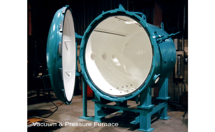
Steel or in selected applications, stainless steel is commonly used for the inner and outer shell construction, to contain the cooling water. If a steel shell is used, it is epoxy coated to promote better pump-down speeds and prevent rusting.
The cooling system water circuit can be either open, closed, or a combination open/closed design. The system is protected against overpressure failure by a safety valve, and flow gauges are provided to monitor the flow rate of the cooling water. Drain ports with ball valves are provided at the bottom of the cooling system to allow draining of the water. There are three main methods of cooling the water, open loop, closed loop, and open/closed loop systems.
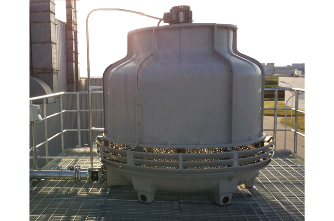
The open-loop cooling system utilizes evaporative cooling by pumping the shell cooling water through a cooling tower (Fig. 8). It is very economical to operate because a great deal of heat is removed via the latent heat of vaporization of the cooling water, and no refrigeration system is required. This type of system is susceptible to buildup of impurities left behind by the water as it evaporates, but this can be controlled through properly timed draining and refill of the water. Since it is open to the shop environment, the cooling water can be contaminated by dirt or dust in the factory.
Figure 8 | Cooling tower (a) External loop and (b) Internal loop
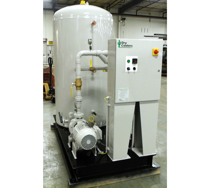
In closed-loop cooling systems, the cooling water is not exposed to the factory air. It is passed through a heat exchanger fitted with a fan to remove the heat. This system minimizes contamination of the cooling water since it is a closed design. It does not, however, take advantage of the latent heat transfer available through evaporation, and therefore has less cooling capacity than the open loop arrangement or the combination open/closed design.
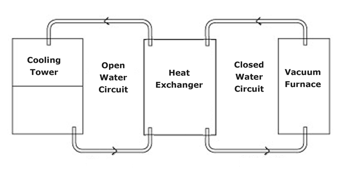
The combination open/closed water cooling design (Fig. 9) combines an open cooling tower loop with a closed loop for the furnace. The cooling tower water on the open side is pumped through a heat exchanger. The other side of the exchanger carries the furnace cooling water in a closed circuit, and the two are thereby kept separate. Since the cooling tower takes advantage of evaporative cooling, large cooling capacity is possible. Because the closed furnace loop is not mixed with the open cooling tower water, the furnace water loop maintains a high level of purity and avoids corrosion of the furnace inner and outer walls, scaling, and accumulation of impurities. As it combines the advantages of both closed loop and open loop systems, the combination open/closed design is a very popular design.
It is important the furnace wall cooling fluid (treated water or an ethylene glycol mixture) be kept above the factory temperature in order to avoid condensation on the furnace exterior or interior walls. At the same time, the circulating coolant must provide sufficient cooling.
A typical design requires the cooling water entering the furnace cooling jacket to be less than 32°C (90°F), with a maximum pressure of 276 kPa (40 PSI). In order to prolong the life of the cooling system and minimize buildup of scale and other contaminants, it is best to use treated water, or tap water. A typical cooling water specification includes a maximum calcium carbonate (CaCO3) content (i.e., hardness value) of 100 ppm, no more than 200 ppm of total dissolved solids, conductivity of 300 microohms per cm, pH between 7.0 and 8.0, and 10 ppm maximum suspended solids.
Summary
Cold wall vacuum furnaces have become the de-facto standard within the industry and have proven themselves highly reliable given what is generally considered routine maintenance. Vacuum designs offer the industry the opportunity to run higher temperatures and to shorten cycle times while maintaining process repeatability and flexibility. These are a major reason why vacuum processing offers the highest quality level in the heat treat industry.
References
1. Herring, Daniel H., Vacuum Heat Treatment, Volume I, BNP Media, 2012.
2. Herring, Daniel H., Vacuum Heat Treatment, Volume II, BNP Media, 2016.
