Applications involving vacuum heat-treating are typically performed for one of the following reasons:
- Processes that can be done in no other way than in vacuum;
- Processes that can be done better in vacuum from a metallurgical standpoint;
- Processes that can be done better in vacuum from an economic viewpoint;
- Processes that can be done better in vacuum from a surface finish perspective.
All of the common (and several uncommon) heat treatment processes can be run in vacuum, from annealing and brazing to sintering and tempering. Many companies that currently outsource vacuum heat-treating ask themselves if they would be better served by setting up this capability in-house. Others who already have an in-house heat treat department wonder if switching to vacuum processing will offer them a competitive edge. This article will help address these questions.
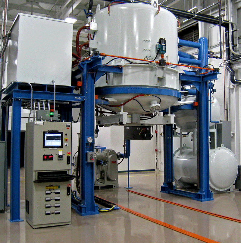
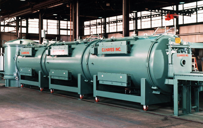
Vacuum furnaces are typically characterized by their method of loading, horizontal or vertical, as well as if there is internal load movement, being classified as either batch or continuous (i.e. multi-chamber) types (Fig. 1 – 2). The various furnaces sizes, production capabilities, and feature configurations are almost endless and detailed extensively elsewhere [1], [2]. Since most vacuum furnaces have a life expectancy of 40 – 50 years, decisions as to what to purchase, and from whom, become very important.
Features
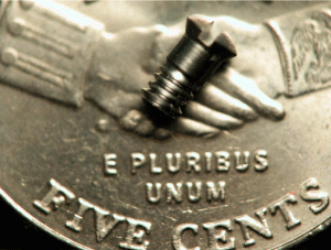
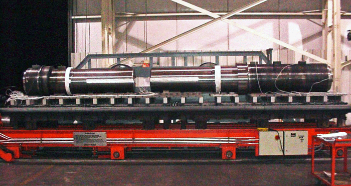
The features necessary for a particular vacuum furnace to run a specific heat treatment process are often determined by results one wishes to achieve, the type and geometry of the component parts to be run (Fig. 3 – 4), the productivity requirements, the physical size of the load, the pressure and temperature to be attained, and the medium (gas or oil) to be used for cooling the load. It is important to recognize that a furnace designed for one application use will in all likelihood be used for many other applications over the span of its lifetime. As such, having the greatest possible flexibility in features and options is highly desirable.
Furnace Design & Construction
The main parts of a vacuum furnace are the:
- Vacuum vessel;
- Pumping system;
- Heating chamber/Hot zone;
- Quench/Cooling system;
- Vacuum and Temperature Controls.
Vacuum furnace vessels can be grouped into so-called hot wall and cold wall designs, the latter being far and away the most common. A typical hot wall furnace has a retort that is commonly metallic or ceramic, dependent on the temperature. The heating system is usually located outside of the retort and consists of resistive heating elements or induction coils. Limitations of this retort-type furnace are the restricted dimensions of the heating zones and the restricted temperature range of the metallic retort, usually limited to 1100°C (2000°F) maximum. With cold wall furnaces, the vacuum vessel is cooled with a cooling medium (usually treated water) and is kept near ambient temperature during high-temperature operations.
Pumping systems are the heart of a vacuum system. Common to most vacuum systems are mechanical pumps, which have the ability to work against atmospheric backpressure and booster pumps used to improve the speed of pump down as well as the level of vacuum that can be reached. Diffusion pumps are a popular option to help reach extremely low vacuum levels while other types of pumps (turbomolecular pumps, cryo pumps) are used to reach ultra-low vacuum ranges.
Hot zone designs vary by type of insulation and materials of construction. In general, they can be classified as:
- All metallic (radiation shields or shield pack)
- Combination (inner metallic shield(s) separated or backed by ceramic or graphite insulation)
- All graphite (board, fiber, carbon-carbon composite)
- All ceramic fiber
Thousands of hours of operating service have confirmed that graphite insulation (felt or board) is suitable for almost all high vacuum applications, including brazing of advanced superalloys. When combined with a hot face of carbon-carbon composite, maximum hot zone life can be achieved, especially in high-pressure gas quenching and brazing furnaces.
It is important that the hot zone support structure be designed to prevent warpage of the internals since, for example,
insulation can crack or gaps can be created through which radiant energy can leak. The structure must be simple and allow a fastening system that avoids undo conductive heat losses while holding the assembly rigid. Hot zone superstructures can be as simple as steel expanded metal mesh or as complex as solid stainless steel enclosures, the latter having the advantage of no rusting and no subsequent outgassing. The critical factor is to help ensure proper temperature uniformity in the workload area and minimize heat loss to the shell.
Another important factor in hot zone design is thermal expansion and contraction, especially important in today’s high-pressure gas quench designs. The expansion rates and temperatures must be taken into careful consideration in the design stage to allow for proper clearances around element supports, nozzles, or restraint systems so that the insulation remains flat with minimal buckling or cracking.
Most vacuum furnaces are electrically heated. Resistance heating elements are constructed from metal or graphite in a variety of styles. The following elements materials are commonplace: stainless steel alloys (300 series) for temperatures to 760°C (1400°F); nickel/chromium and iron-aluminum based alloys to temperatures of 900°C (1650°F); Inconel® and other nickel alloys for use to 1150°C (2100°F); silicon carbide (SiC) for operating temperatures to 1090°C (2000°F); molybdenum to achieve 1700°C (3100°F); graphite for use up to 2000°C (3630°F); tantalum, typically to 2400°C (4350°F) and tungsten to reach 2800°C (5075°F).
The choice of a heating-element material depends largely on operating temperature. For low-temperature operations such as aluminum brazing or vacuum tempering, inexpensive stainless steel or nickel-chromium alloys can be used for the heating elements. For higher-temperature general heat-treating applications such as hardening, or brazing, graphite or molybdenum are popular choices for element materials. Lightweight, curved graphite elements are becoming increasingly popular for vacuum furnaces. These elements have the advantage of lower thermal mass and have excellent structural integrity. For specialized heat-treating applications above 1480°C (2700°F), graphite or refractory metals (tantalum, tungsten) are popular choices. Still other processes such as low-pressure vacuum carburizing use graphite or silicon carbide elements.
Quench (cooling) systems are typically either oil or (high pressure) gas. Many companies use oil quenching to achieve consistent and repeatable mechanical and metallurgical properties and predictable distortion patterns. The reason oil quenching is so popular is due to its excellent performance results and stability over a broad range of operating conditions. Oil quenching facilitates hardening of steel by controlling heat transfer during quenching, and it enhances wetting of steel during quenching to minimize the formation of undesirable thermal and transformational gradients which may lead to increased distortion and cracking.
Gas pressure quenching has seen a tremendous rise in popularity in recent years and its success is highly dependent on a number of factors including material, component geometry, loading, net to gross load ratio, gas parameters, and equipment design. Pressure ranges span sub-atmospheric, low, medium, high and ultra-high pressure (up to 25 bar in commercial practice) irrespective of the type of gas used.
There are two popular quench cooling loop designs available for vacuum furnaces, internal and external. While cooling performance criteria are very similar for both designs, each has some advantages and drawbacks. Furnaces with internal heat exchangers have the advantage of a compact design. The furnaces occupy slightly less floor space than those with a similarly sized external cooling loop. Its chief drawback is the close proximity of the quench blower motor (including drive shaft and bearings) to heat emanating from the furnace hot zone. If a failure of a motor component or heat exchanger does occur, it is often necessary to remove the entire hot zone to gain access for repairs. There is also the risk of damage to the furnace internals, and possibly the load if the heat exchanger should ever develop a water leak.
In the external quench loop design, the blower housing, heat exchanger housing and quench piping are located outside the vacuum chamber. The external quench loop design permits easier maintenance access to the blower and heat exchanger. The external loop design also minimizes the occurrence of quench blower failures by isolating sensitive components from exposure to heat from the vacuum chamber. Furthermore, any water leaks that might occur in the heat exchanger are confined within the separate heat exchanger housing.
Vacuum furnace process control systems (Fig. 5) are somewhat similar to atmosphere furnace control systems; however, they tend to be somewhat more sophisticated, especially from a temperature control standpoint. As they continue to evolve, even the most basic control systems often include easy-to-read digital displays and touchscreens with graphics to display operating parameters and alarms. Where more advanced data management applications justify the higher cost; the PC-based control system is a user-friendly and versatile tool. Perhaps their biggest advantage is the ability to access information that allows the user to analyze, adjust and download operating parameters from remote locations. These systems can be connected to local networks for multiple user access and even to the Internet via secure connections.
Most of today’s temperature control systems involve “adaptive” process control. Depending on the machine or process, different variables exist that must be monitored, controlled and/or changed during the cycle. Sensors monitor a selected process or equipment parameter; send the gathered data back to a controller, which then compares it to a predetermined value or set point. Through calculations, a controller sends a signal back to the device to make the proper adjustments to obtain a controlled process. Programmable Logic Controllers (PLC’s), sensors, and computers make this all possible. In turn, data trending, real-time process monitoring, and data collection for permanent retention are commonplace. By analyzing this data, new cycles, containing modified variables, can give better results in less time.
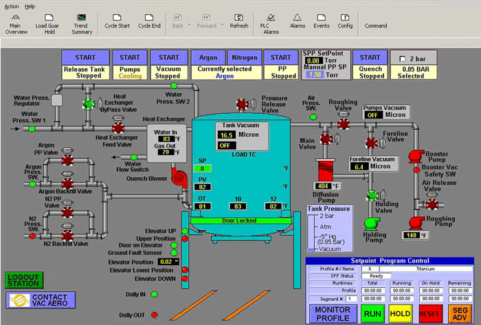
Vacuum controls depend to a great extent on the type of vacuum system and the required operating vacuum level. For each operating range, different vacuum gauges are required, often in combination with one another, to accurately determine and/or control the vacuum level of the chamber at any given moment in time. The criteria for selecting a vacuum gauge are dependent on various conditions such as:
- The vacuum range to be detected;
- The gas composition (inert, reactive, corrosive);
- Required accuracy and repeatability;
- Environmental conditions.
Vacuum gauges are divided into three basic categories based on their working pressure. These include absolute pressure gauges; vacuum gauges useful down to around 0.001 mbar (1 micron); and vacuum gauges for use below 0.001 mbar (1 micron).
Used Equipment
The purchase of a vacuum furnace involves a considerable capital investment. As a result, the question of buying a used furnace often at a lower cost than a new furnace is a fairly common one. Most used furnaces are sold on an as-is, where-is basis with no manufacturer’s warranty. One of the most important issues to assess is the condition of the vacuum chamber water jacket. In situations where the furnace cooling system has been connected to an untreated water supply, water jacket blockages from mineral build-up are all too common, and moving the furnace triggers untold problems. Ultrasonic testing of the shell is a good first step, as is looking for discolored or blistered paint, a sure sign of overheating.
The condition of the hot zone, heating elements, pumping system, and vacuum controls must also be considered. A thorough visual inspection is usually the first step in the process as is consultation from various suppliers of the component on the system. For example, when looking at the condition of the hot zone, distorted, discolored or crumbling insulation, warped or broken elements or hearth rails, missing element insulators, and other damaged hardware are all signs that restoration work is required. All-metal hot zones are often more expensive to repair.
The control system is another important consideration when evaluating used furnaces. Having State-of-the-Art controls is highly desired and with technology obsoleting itself at an extremely rapid pace, even 10-year-old control systems can be problematic.
In Conclusion
The right vacuum furnace is the one that performs the intended application with the highest degree of uptime productivity and uncompromised quality. While an array of business decisions must be made to justify the expense, it is comforting to know that today’s vacuum furnaces offer the latest technological advances in furnace design (hot zone materials, control packages, and quenching systems) and offer many operating and performance improvements. It is often advisable to look to companies who have proven experience both as a heat treater and furnace manufacturer. This type of knowledge will shorten the learning curve.
References
- Herring, Daniel H., Vacuum Heat Treatment, BNP Media Group II, 2012.
- Herring, Daniel, Heat Treating Equipment: Types and Selection Criteria, white paper, 2010.
- Herring, Daniel H., Saving Money by Maximizing Furnace Uptime Productivity, Industrial Heating, January 2013.
- Important Considerations for Establishing a New Vacuum Heat Treating Capability, white paper, Vac Aero International.
- Buying a Vacuum Furnace, New Versus Used, white paper, Vac Aero International.
- Vacuum Furnace Quenching Systems: External versus Internal, white paper, Vac Aero International.
