Cleaning in a solvent offers a level of simplicity and forgiveness not seen in aqueous methods. At one time solvent cleaning was considered mandatory for successful vacuum processing but environmental concerns (VOC and other emissions) and improvements to aqueous systems including drying technology has seen the industry shift to aqueous cleaning as the norm. Today, however, with the advent of vacuum technology, vacuum vapor degreasing has emerged as a viable alternative to aqueous processing.
Solvent cleaning involves three basic steps: wash, rinse and dry. Washing is where the parts are immersed in or placed in contact with a (typically boiling) solvent to assist with the contaminant removal process. The purpose of rinsing is to bring “fresh” or clean solvent in contact with the parts. The aim is to dilute the contaminated solvent present on the surface of the parts from washing. It is important to remember that the rinse solvent must be kept clean. Contaminated solvent is a very common problem and will only reintroduce contaminants back onto the surface. The drying step evaporates the solvent and separates the rinse solvent from the parts.
Older Technology
Traditionally, solvent based degreasers depended on the application of heated solvent vapors in an open tank to accomplish the required cleaning tasks. The concept of heated solvent vapor cleaning is a simple one. Heated solvent vapors are drawn to the cooler surface of the parts to be cleaned. These vapors are actually drawn “ through “ organic contaminates by this temperature differential and in the process solubilize and flush off both organic and inorganic contamination.
The principle behind the vapor degreasing process is that a solvent can be used to dissolve then remove contaminants found on most parts by condensation. The basic idea is as follows: A tank of solvent is set up with a heating coil to bring the solvent to boil. As the solvent evaporates it rises to the fill-line in the chamber, above which is air with a much lower density than the solvent (often cooling coils are installed to reduce the amount of solvent released to the atmosphere). This contains the vaporized solvent in a closed space where the workpiece is placed. The solvent condenses on the more frigid workpiece and the now liquid solvent dissolves the contaminants (oils, greases, dirt, etc.) on the part. With the impurities contained in the liquid beads, the solvent runs off the part. Some systems are designed to capture and reclaim this solvent, making the process much more economical.
Vacuum Vapor Degreasing Technology
Today, vacuum vapor degreasers (Fig. 1) have dramatically improved upon and replaced the traditional open tank method of vapor degreasing by placing the process in a sealed vacuum environment, which employs a programmed sequence of heated vapors and cool solvent sprays. Emissions are virtually eliminated.
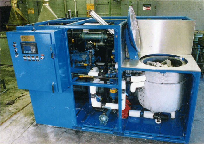
This cleaning sequence first allows the solvent vapors to be drawn into all areas of the parts and the load, including difficult to reach locations, such as blind holes, crevices and inverted “cups”. Due to the vacuum nature of the process, there is no air” bubble” in these tight areas to interfere with the solvent vapors reaching all surfaces. As the solvent vapors condense on the part surfaces, the surface temperature rises and the effect of vapor cleaning is reduced. At this point, the cool solvent is sprayed onto the parts to lower the surface temperatures and flush the parts. When the spray phase has ended additional heated vapors are again introduced into the cleaning chamber and vapor cleaning is begun again. This sequence can be repeated a number of times.
A typical sequence would three two minute vapor phases and several (2 – 3) thirty-second spray phases. This sequence provides a method of applying only freshly distilled solvent to all surfaces that are being cleaned rather than create a cross contaminations situation as is often done in solvent immersion cleaning. Additionally, the use of sequenced vapor and spray reduces the volume of solvent that is being sent to distillation. Lower volumes of contaminated cleaning solvent being distilled greatly reduces the amount of energy that is used to distill and condense the solvent resulting in lower initial equipment and operating costs.
The sequenced vapor spray technique is managed by the PLC and is variable in time and temperature and frequency which means that it is possible to “ custom “ design a cleaning process to the specific part and configuration that is being cleaned. Since cleaning is being done in a sealed chamber, the spray function can be designed to be mild to very aggressive, and since total solvent volume being used are smaller than immersion methods, this technique actually provides more cycle time to be dedicated to actual cleaning rather that chemistry management.
Sequence of Operation
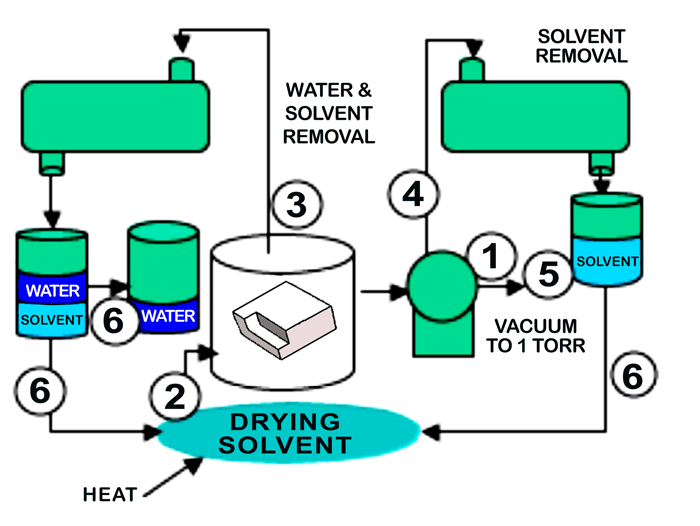
In operation (Fig. 2), the parts to be cleaned and dewatered are placed in the vacuum process chamber, and the following sequence of operation takes place:
1. A vacuum is pulled to about 1 Torr.
2. At this point, heated solvent vapors are brought into the cleaning chamber and allowed to condense on the parts. The transfer of heat by solvent vapors is very fast when compared to the transfer of heat by air.
3. As the parts heat, the water on and within the parts being processed, flashes off the parts under vacuum and the exiting water-solvent vapor mixture leaving the process chamber is directed to the water management module. As the water flashes off, the parts would tend to cool except for the fact that as the parts begin to cool they attract more heated solvent vapors, thus keeping the parts hot until all the water has been flashed off of and from within the part. At this point, the parts are free of water and can rise to the operating temperature of the solvent. With the water removed future steps such as immersion, rotation, etc., can be applied as needed to complete the cleaning of the manufacturing contaminants.
4. After the water removal, the heated part can now be dried of the solvent by vacuum since less solvent is present than the original volume of water, the part now holds more heat than the water soaked part and because the latent heat of vaporization of the solvent is much lower than water.
5. After vacuum drying, the chamber is reduced to 1 torr to assure recovery of all solvent.
6. Finally, the solvent can now be separated from the water and be recycled for future use.
Summary
Solvent cleaning has a negative connotation in the heat-treating industry primarily due to environmental concerns, safety and cost issues. The emergence of vacuum vapor degreasing in a sealed vessel offers an attractive alternative that takes advantage of the best aspects of solvent cleaning. The size and amount of residual contaminants are reduced while meeting the most stringent cleaning requirements and avoiding the traditional problems of open degreasing systems.
Vacuum vapor degreasing comparison between air drying and vacuum drying methods.
Drying in Aqueous Systems
In aqueous systems, heated air-drying is the most common method used for water removal. However, it is fair to say that most aqueous washers do a poor job of effective drying. Generally, ambient air is employed, which depending on the relative humidity can contain significant water vapor, to begin with. Upon heating the air becomes saturated and if the temperature can be maintained, can evaporate a considerable amount of water. The problem, however, is not usually in the saturation levels of the air, rather in the heat and mass transfer operations required to accomplish the water removal.
The rate of drying is dependent upon the mass transfer driving force created between the water surface and the heated bulk air. The vapor concentration at the water droplet surface is totally dependent upon the temperature to which one can heat the droplet. The bulk air moisture content is totally dependent upon the air source used for drying. It is therefore clear that the initial task in air-drying is to heat the surface of the part or droplet in order to increase the water concentration at the drop surface (that is, the vapor pressure of the liquid).
The heated section of an aqueous washer, or for that matter an air oven, transfers heat to a component part by natural convection. The natural convection method is very slow with respect to the rate of heat transfer (Equation 1) which is given by:
(1) Q = U Δ T
Where U, which is known as the heat transfer coefficient and can be considered a measure of the effectiveness of the heat transfer process, generally falls in a range of between 1 and 5 BTU / (ft2-hr-°F). Delta T (ΔT) is the driving force for heat transfer, which in this case is the temperature of the air minus the temperature of the water drop or solid surface.
The drying process is generally very slow under these conditions even with fans moving the air from the heating source to the part surface. Under forced convection conditions, U generally can be increased to between 55 – 170 W/m2-hr °K (10 to 30 BTU / ft2-hr-°F). Forced convection can increase the heat transfer from 2 to 30 times that of natural convection.
However, the heat transfer is only half the task, during the heating of the water droplets, vapor at the droplet surface becomes more concentrated than the water vapor in the bulk air and begins to diffuse into the bulk air, The rate of transfer is given by (Equation 2)
(2) N = k Δ C
Where k is called the mass transfer coefficient, N is natural convection and Delta C (ΔC) is the water vapor concentration difference between the droplet surface and the bulk air.
As with the heat transfer coefficient, the value can be greatly increased with forced convection versus natural convection. The mass transfer of water from the drop to the bulk air removes heat from the drop since the specific heat of the water vapor, and more importantly the latent heat of the water vapor evaporating from the drop to replace the vacating water vapor, cooled the drop and acts to counter the incoming heat carried by the air.
Drying in Vacuum Solvent Systems
Another method used to dry water from parts is by the use of a vacuum to reduce the bulk concentration of water vapor in air. The vapor at the droplet surface immediately diffuses as the vacuum is reduced and the concentration difference is maintained by constantly removing the evaporating water. Since heat is not transferred, the diffusion process is very rapid. The droplet and parts surface begins to cool as the heat is transferred to the escaping vapor. If the water does not completely evaporate before the part cools below 0ºC (32°F), ice can form and the process will dramatically slow down ((since the ice now must sublime into the surrounding vacuum.) Since the vapor pressure of ice is very low, the driving force Δ C becomes very small even if a total vacuum is attained. Typically at this point, it is more beneficial to use forced air convection.
Vacuum Drying Process
The goal in vacuum drying is to remove all the air from the drying chamber. Upon removal, a heated vapor using an insoluble solvent is introduced into the chamber. The condensing vapor acts as a heat transfer medium. This process is similar to condensing steam and can be described by Equation 1 (above). The heat transfer coefficient, in this case, is 570 – 1700 W/m2-hr °K (100 – 300 BTU /ft2-hr-°F) and thus up to 3 – 30 times faster than forced convection heat transfer.
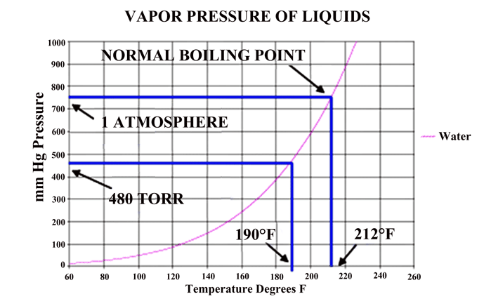
In a vacuum, the pressure in the chamber can only reach the vapor pressure of a liquid if a liquid phase is present in the chamber. The vapor pressure is depended upon the temperature of the liquid present (Fig. 3) shows.
For insoluble liquids, they exert their own vapor pressure and thus the amount of vapor is actually additive under these conditions (Fig. 4). Under these conditions, water droplets heat rapidly and diffuse quickly into the vapor state. If this mixture is continuously removed, the water concentration in the vapor state can be kept low and the diffusion rate high. The continuous addition of solvent vapor can maintain the temperature and can easily be separated from the water after condensation.
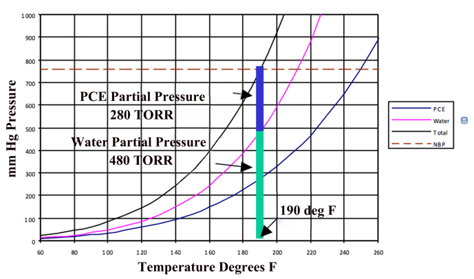
The phase diagram for a water-PCE mixture (Fig. 5) shows us that for equilibrium conditions at one (1) atmosphere, one can expect that a PCE heated solvent heated will enter the chamber at 120°C (250°F). The exiting vapor can be expected to be rich in water vapor and approach the equilibrium mixture of 63% water up until there is essentially no water remaining on the part, The temperature of the drying is approximately 90°C (190°F), which would be equivalent to drying water at 480 Torr.
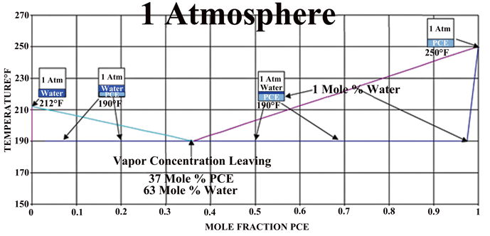
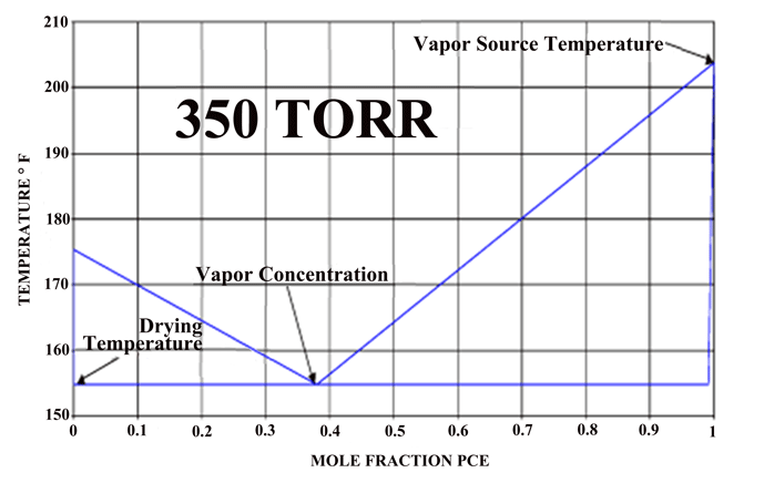
If one compares the drying method above to the conventional oven or vacuum drying methods, both the heat and mass transfer can be an order of magnitude higher. This translates into drying times measured in minutes rather than hours as usually encountered in industrial water drying of difficult parts. A phase diagram of an actual system (Fig. 6), which operates under vacuum, can be seen that by controlling the pressure of the system one can vary the actual drying temperature.
Summary
A process that provides for the best of both air-drying and vacuum drying is highly desirable. It will provide both a medium to carry heat to the part (as in air-drying) and a faster and more complete method of removing water on the parts (as in vacuum drying). In addition, it requires less of a vacuum to dry at lower temperatures.
REFERENCES
- Wikipedia (www.wikipedia.org)
- Herring, Daniel H., Vacuum Heat Treatment, BNP Media, 2012.
- Gray, Donald and Joseph P. Schuttert, “Removal of Entrained Moisture from Powdered Metal Parts Using High-Temperature Solvent and Vacuum” PM2TEC 2003.
- Herring, Daniel H., “It’s Time to Clean Up Our Act!”, Industrial Heating, 2008.
- “Hyperflo Sequenced Solvent Vapor-Spray Cleaning Technique, white paper.
