BY JEFF PRITCHARD
Most base metals typically brazed in vacuum furnaces have a natural oxide “coating” that can inhibit the flow of brazing filler metals.
Conversely, alloys containing appreciable amounts of reactive elements such as aluminum and titanium tend to form oxides at high temperatures which impede the flow of the brazing filler metal. Many of the nickel-base superalloys fall into this category and the severity of the problem varies depending on alloy composition. These materials should be brazed at high vacuum levels of 2 x 10⁻⁴ torr or better. There are several reliable techniques for improving the brazeability of difficult to braze materials. These include brush nickel plating of the joint surfaces, chemical etching techniques to remove aluminum and titanium from a shallow layer at the joint surface and using special aggressive braze filler metals with self-fluxing characteristics. The oxides of the less reactive metals like iron, nickel, and cobalt tend to dissociate (break down) under low pressure and high temperature. Therefore, alloys such as the 300 and 400 series stainless steels, carbon steels and many tool steels can be successfully brazed in vacuum at relatively high pressures (1 to 50 microns).
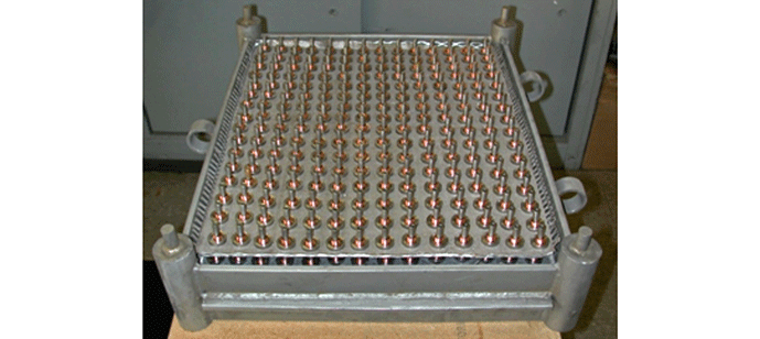
Titanium and zirconium base alloys can be vacuum brazed using specially formulated braze filler metals. Because of their tendency to become contaminated by even small amounts of oxygen or moisture these alloys must be brazed at high vacuum levels in a clean furnace. Aluminum and many of its alloys can also be brazed in vacuum. However, aluminum alloys are normally brazed in dedicated furnaces designed for maximum temperature uniformity at temperatures less than 650ºC (1200ºF). Outgassing of magnesium during brazing of many aluminum alloys will quickly contaminate furnace equipment and loads subsequently processed at higher temperatures. For these reasons, it is strongly recommended that vacuum brazing of aluminum be performed in dedicated furnaces only.
Vacuum brazing of dissimilar metals can be readily accomplished provided that differences in thermal expansion are taken into account. If a base metal component with a high coefficient of thermal expansion surrounds one with a lower coefficient, joint clearances that are satisfactory for capillary flow at room temperature may become too large at the brazing temperature. The converse can also occur, where tightening of the joint at the brazing temperature prevents alloy from flowing within. Thermal expansion calculations should be made for all “ring in plug” type joints involving dissimilar metals. For complex configurations, it may also be necessary to conduct pre-production trials to determine proper joint clearances.
Brazing involves the joining of two or more base metal components by melting a thin layer of filler metal into the space between them.
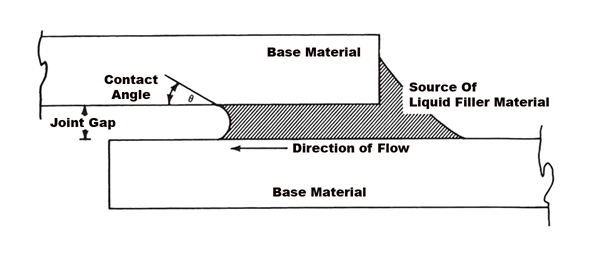
Bonding results from the intimate contact produced by the dissolution of a small amount of base metal into the filler metal, without melting of the base metal. Brazing differs from welding, in which the joint is formed through melting of the base metal. Brazing is similar to soldering but, by definition, is performed at higher temperatures. In brazing, the filler metal can be placed within the joint as a foil, or placed over the joint in the form of paste or wire. Joint clearances must be very carefully controlled and usually do not exceed .12mm (.005″). Capillary action draws the molten filler metal into the joint and holds it there. The base metal components must be designed to enhance the capillary action. Brazing is a process that has been well adapted to vacuum heating methods.
There are several factors that must be considered when selecting a brazing filler metal or braze alloy, for a particular application. The melting points of the base metal and braze alloy are perhaps the most important. Pure metals transform from the solid to the liquid state (melt) at a single temperature. However, many metallic materials are alloyed by adding other elements to produce certain desired characteristics. Rather than completely melting at a single temperature, most alloys melt over a temperature range. The temperature at which they begin to melt is known as the solidus temperature. The temperature at which they become completely molten is called the liquidus temperature. While at temperatures in the melting range between the solidus and liquidus, both solid and liquid phases are present. When selecting a braze alloy, it is important to ensure that the melting range of the braze alloy does not overlap that of the base metal. As a general rule, the solidus of the base metal should be at least 55ºC (100ºF) higher than the liquidus of the braze alloy. For brazing stainless steels and materials intended for use at high temperatures, there are a wide variety of commercially available braze alloys that meet these criteria. Some compositions are designed with narrow melting ranges for ease of use in applications where joint clearances are adequately controlled. Others have wider melting ranges and can be used to fill large joint clearances.
 The compatibility of the braze alloy with the base metal must also be considered. There is almost always some interaction between the braze alloy and base metal, the extent of which varies depending on compositions and the thermal cycle. Under certain conditions, molten braze alloy can dissolve base metals creating an undesirable condition known as erosion. The constituents of the braze alloy can also diffuse into the base metal causing a change to base metal properties such as embrittlement. This can be particularly damaging if the base metal is thin. Whenever excessive base metal dissolution is likely to occur, brazing should be performed in as short a time and at as low a temperature as possible. Sufficient braze alloy should be present to completely fill the joint, but excessive amounts should be avoided.
Braze alloys containing appreciable amounts of volatile elements may need to be brazed under a partial pressure of a gas such as hydrogen or argon. Copper base braze alloys and those containing zinc, cadmium, and manganese as melting point suppressants are typical examples. Some silver base and even nickel-base braze alloys also require the use of partial pressures to prevent vaporization of key alloying elements.
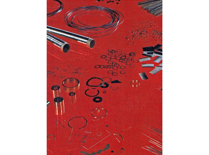
When selecting a braze alloy, it is important to consider the manner in which the alloy will be introduced into the joint and the form in which it is commercially available. Ductile metals such as copper, silver and gold base braze alloys are available in the form of wire, shim, sheet, and powder. Shim and sheet can be pre-placed directly in the joint during assembly of the components to be brazed. Nickel base braze alloys are brittle and are usually supplied in the form of powder. These can be mixed with binders to form a paste that is easily applied over the joint. Joint design has some influence over which form of braze alloy is preferred. For thick joints, pre-placement of the braze alloy may be necessary to ensure the joint is completely filled. Also, different braze alloys often require different joint clearances for effective capillary flow
Clean, oxide-free surfaces are essential to achieving sound brazed joints.
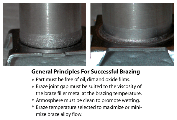
Uniform capillary action will occur only when all grease, oil, dirt, and oxides have been removed from both the braze alloy and base metal prior to brazing. The length of time that cleaning remains effective depends on the material involved, atmospheric conditions, storage techniques and the amount of handling that may be involved. It is recommended that brazing is performed as soon as possible after the material has been cleaned. The selection of a cleaning technique depends on the nature of the contaminant, the base metals involved and the joint design. The same cleaning practices used for vacuum heat treating (ie. manual cleaning, vapour degreasing, etc.) are applicable to vacuum brazing.
After the materials to be brazed are thoroughly cleaned, the braze alloy is applied. Proper application of braze alloy is best learned through practice but a few general rules apply. Excessive application of braze alloy should be avoided, particularly when brazing thin sections with aggressive fillers. The volume of braze alloy applied should be carefully considered, especially when using braze alloys in the form of a paste. Pastes may contain more than 50% binder so the size of the bead applied compared to the actual amount of braze alloy delivered can be deceiving. Although braze alloy will flow “uphill” due to capillary action, it should be positioned over the joint to take advantage of gravitational forces whenever possible. During application of pastes, joints should not be completely sealed. Each joint must be allowed to vent during pump-down of the vacuum furnace. Stop-off paints can be used to limit the flow of braze alloy into unwanted areas. However, for some applications, additional cleaning may be required to remove oxides. Mechanical cleaning methods such as grinding, wire brushing, machining or blasting are often used to remove oxides or other objectionable surface conditions. They can also be used to roughen joint surfaces which may promote braze alloy flow. Care must be taken to ensure that no residues of the cleaning media are left on joint surfaces.
Components to be joined by brazing must be assembled in a fixed position relative to each other and this position must be maintained throughout the brazing cycle. During assembly, care should be taken to ensure that proper joint clearances are also maintained. Whenever possible, parts should be designed so they are self-fixturing. If this is impractical, tack welding is the next best alternative. However, some assemblies may require auxiliary fixturing. Fixturing materials with coefficients of thermal expansion similar to the base metal should be used. Auxiliary fixtures should be low in mass and simple in design.
The use of screws or bolts should be avoided. Threaded fasteners tend to sinter together at high temperatures and are difficult to remove. If springs or clamps are required, these must be able to withstand the temperatures to which they will be exposed during brazing. When using metallic fixtures, all points of contact with the brazed assembly should be masked with stop-off paints. Finally, fixtures should be cleaned and vacuum baked before use to remove all sources of contamination
There are a number of factors that influence the development of a brazing cycle. These include such things as base metal and braze alloy composition, and mass of the assembly and joint design.
However, each cycle is comprised of a number of common segments. The illustration below shows the typical profile for a vacuum brazing cycle. During the initial pump-down, water vapor adsorbed by the parts and furnace is driven off. For most brazing applications, a pump-down before heating to a vacuum level of 8 x 10⁻⁴ torr or better is recommended. A vacuum safety interlock should be programmed into the cycle to ensure this level is reached. After pump-down, the initial heating rate should not exceed 15ºC (30ºF) per minute. Faster rates may cause paste braze alloy to spall off or distortion of the assembly. Heating continues to a stand-off temperature at about 25ºC (50ºF) below the solidus temperature of the braze alloy. The load is then soaked at this temperature to ensure temperature uniformity and to allow vacuum levels to recover. A soak time of 30 minutes is usually sufficient, though the incorporation of a second vacuum safety interlock in the braze cycle program may be desirable.
At the conclusion of the soak, a faster ramp rate of 15ºC to 25ºC (30ºF to 50ºF) per minute is employed to heat the load to the braze temperature. The rate must be fast enough to prevent “liquation” of the braze alloy where lower melting point constituents begin to melt separately. A faster heating rate also reduces the risk of erosion of the base metal.
 The brazing temperature should be the lowest possible within the recommended range. For many braze alloys, the minimum brazing temperature will be at least 25ºC (50ºF) above the liquidus temperature. Minimum brazing temperatures are essential when using free-flowing braze alloys, when trying to braze large gaps and when brazing thin materials. At lower temperatures, molten braze alloy will be more sluggish and less reactive with the base metal. The time at brazing temperature should be just long enough to ensure that all sections of a part and all parts within the load reach the desired temperature. This time normally ranges between 5 and 10 minutes but may be longer for heavy loads. When the braze soak is complete, the cooling cycle can begin. Unless a specific heat treatment is required, it is strongly recommended that the load be cooled to a temperature at least 25ºC (50ºF) below the solidus temperature of the braze alloy before gas quenching is initiated. This will ensure that molten braze alloy has re-solidified and will not be blown away from the joint during the quench.
Despite taking all necessary precautions, joint defects will occasionally occur. Fortunately, defects can often be repaired by re-brazing. Because of diffusion and mixing of constituents between braze alloy and base metal, most braze alloys tend to develop a higher re-melt temperature after the initial braze. Rather than attempting to repair the joint defect by re-melting the existing joint, it is better to apply a small amount of additional alloy in the defective area. To prevent re-melting of the existing joint, a re-braze temperature lower than that used in the first braze is preferable, particularly if wide joint gaps are involved. The defective area should be re-inspected for cleanliness before additional braze alloy is applied. The brazing cycle can then be repeated as before, with modifications to the brazing temperature.
