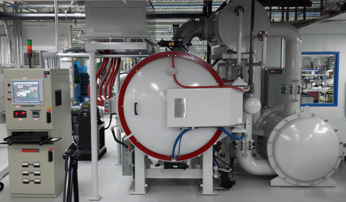
A Vacuum Gauge is a pressure measuring instrument that measures pressure in a vacuum (i.e., in a vessel operating at sub-atmospheric pressure). Depending on the type of vacuum system (Fig. 1) and the required operating vacuum level, different vacuum gauges are required, often in combination with one another, to accurately determine and/or control the vacuum level of the chamber at any given moment in time.
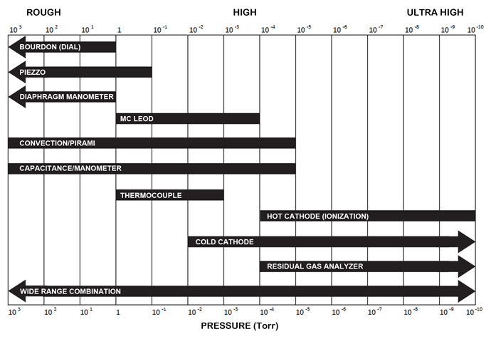
Vacuum gauges are basic measurement components for vacuum furnace systems and can be found either in vacuum lines or connected directly onto the vacuum chamber. For all intents and purposes, a vacuum gauge is an instrument for measuring pressures below that of atmospheric pressure. There are several types of vacuum gauges, each engineered for a specific function over a specific range of vacuum pressure (Fig. 2). Common types (Table 1) include:
- Mechanical gauges
- Absolute pressure gauges
- Thermocouples or Pirani gauges
- Ionization gauges (hot & cold cathode)
- McLeod gauges
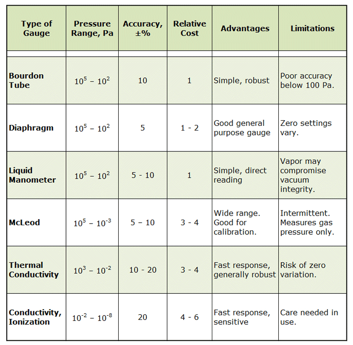
Notes: 1. Relative cost based on a unit price of 1
Selection Criteria
The criteria for selecting a vacuum gauge are dependent on various conditions such as:
- The vacuum range to be detected;
- The gas composition (inert, reactive, corrosive);
- Required accuracy and repeatability;
- Environmental conditions.
Questions to Ask When Selecting Vacuum Gauges
When considering the purchase of a vacuum gauge, here are some of the basic questions to ask yourself:
- What pressure range are you looking for?
- What accuracy range are you seeking?
- Are there any other ranges that are important?
- Do you need to control or regulate, in addition to measuring?
- What form (panel mounted or desktop) gauge are you looking for?
- What kind of power do you have/need?
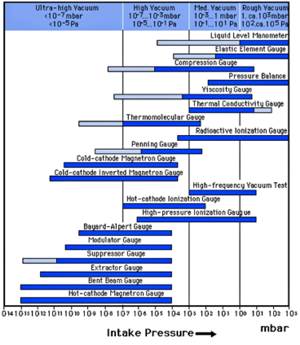
Vacuum gauges are divided into three basic categories based on their working pressure (Fig. 3). These include:
- Absolute pressure gauges;
- Medium vacuum gauges – useful down to around 0.001 mbar (1 micron);
- High vacuum gauges for use below 0.001 mbar (1 micron).
Sage Advice from Howard Tring
A few years ago, in an article titled Vacuum Gauges Used on Vacuum Furnaces author Howard Tring offered these insights into the world of vacuum gauges when he told us:
“Vacuum gauges measure the pressure readings in the range from atmospheric pressure down to some lower pressure approaching absolute zero, which is not attainable. Some gauges read the complete range with low resolution and others can only read a portion of the range but with better resolution, usually used for the lower pressures.
There are three groups of vacuum gauges based on the method of operation, mechanical, thermal conductivity, and ionization. For this discussion, we will only talk about the thermal conductivity and ionization gauges because purely mechanical vacuum gauges are generally not used on vacuum furnaces.
A typical electrical vacuum gauge consists of a sensing head (gauge head) and a readout. It has a power cable to supply power (115V) to the readout and an electrical cable to supply power to the gauge head and also to carry the signal from the gauge head to the readout. Gauge heads are usually mounted vertically, i.e. with the connection downwards. This is to allow the gauge heads to read correctly and also to prevent debris from entering the head.
For systems such as vacuum furnaces the high vacuum gauge most used is the Penning cold cathode gauge that indicates pressure from the 10-2 Torr decade down to around 10-9 Torr. It has a robust stainless steel gauge tube and can be dismantled and physically cleaned if it becomes contaminated is actually a Wide Range Active gauge head and incorporates a small Pirani head inside the Penning gauge tube. The Penning type gauge is bulkier than other gauge heads due to the magnets mounted around the gauge tube.
In recent years the measuring range of capacitance manometer gauges has been improved that now models can read pressures down to about 10-5 Torr. This allows them to be useful for some high vacuum processes because the heads are also corrosion resistant and are the most accurate vacuum gauge available.
For measuring foreline pressure and chamber roughing pressure there are several options. The thermocouple gauge (TC), the Pirani gauge and the Convection gauge. The convection gauge is a hybrid design of the Pirani gauge to enable readings at higher pressures. They all read from about 20 Torr down to about 1 x 10⁻³ Torr (1 micron) and have a good resolution from 1 Torr to 1 x 10⁻³ Torr.
Often, US-made TC and Convection gauge heads are supplied with a 1/4″ NPT threaded connection as standard. Threaded connections are difficult to seal for use in vacuum systems as there are often small leaks through the root and crest of the threadform. (How many of these gauge heads have you seen with the black sealing compound stuck around the connection?) The modern “NW” rubber O-ring connection is a much better option, much less prone to leak and easier to put on and take off.”
You might be interested to know that gauge development continues to advance and here is a brief look at some of the more interesting recent advances.
Types of Gauges
Passive Vacuum Gauges10
Traditional vacuum gauges (aka vacuum sensors, transducers, and/or vacuum tubes) are considered passive gauges and including such sensors as thermocouple gauges, convection gauges, diaphragm gauges (for low vacuum measurement) and cold cathode gauges or hot ion gauges (for high vacuum measurement). All passive vacuum gauges require a vacuum controller or an active vacuum gauge (see below) in order to provide vacuum.
Active Vacuum Gauges10
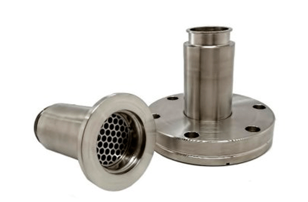
Active gauges (aka digital vacuum gauges, smart gauges) combine the passive vacuum gauge and vacuum controller electronics in one device. These gauges often feature thermocouple gauges, convection gauges, and cold cathode gauge technology bundled together to provide a full range vacuum measurement from atmosphere to ultra-high vacuum applications. These gauges are especially attractive when frequent calibration and/or sensor replacement is needed as they can be easily disassembled, cleaned, and calibrated or replaced. In particular dirty applications, you may consider the use of an in-line filter before the gauge.
Vacuum Controllers10
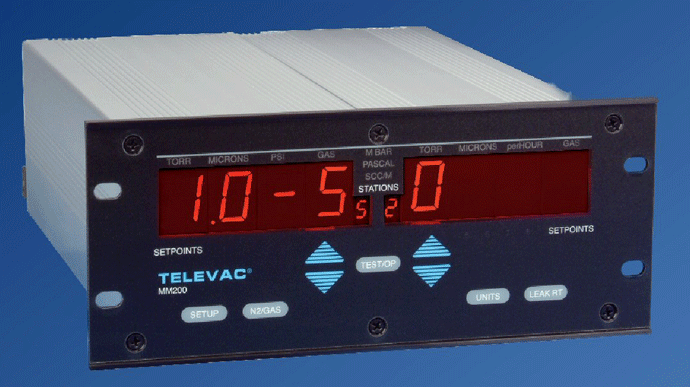
Vacuum controllers (Fig. 4) are designed for use with passive vacuum gauges and each style has certain offers unique features and benefits. For example, rack-mountable controllers, can control multiple vacuum gauges (typically between 2 and 10) and are configurable to meet a number of specific requirements. These devices are also easily integrated into a plant network. Portable vacuum controllers often control one thermocouple gauge to provide high-precision sensing technology in a compact, self-contained package.
Adapting Gauges to Shop Floor Environments
Manufacturing environments can be problematic for sensitive instrumentation and vacuum gauges and sensors are prone to damage, drift and other issues in any shop environment. Remember that some form of contamination (e.g., oil vapors, dirt) is always present. Here are some hints on common types of vacuum gauges to extend their life:
Improving Contamination Resistance
- Use Pirani, thermocouple, convection technologies (thermal conductivity gauges) whenever possible.
- Use of macro versus micro (MEMS) sensors since the latter are more susceptible to contamination, particularly in heat treat/vacuum furnace applications and require more frequent calibration and/or replacement. MEMS sensors often include electronics, adding to replacement costs.
Use Digital Calibration Methods
- Historically, calibration methods were analog in nature, performed with potentiometers (aka run-up pots). Today, many gauges and controllers have digital displays, which allows calibration at gauge.
- Digital calibration can be done via digital communications (e.g., EtherNet/IP, RS-232, RS-485, and others). This prevents a mismatch between HMI and the display. It also allows for the integration of calibration into the HMI.
Here are the most common types of gauges found on vacuum systems.
Mechanical Gauge Designs
Mechanical gauges measure pressure or vacuum using some form of mechanical deformation of tubes or diaphragms exposed to differences in pressure. For this reason, they are generally classified as differential-pressure gauges. Typically, one side of the element is exposed to reference vacuum, and the instrument measures the mechanical deformation that occurs when unknown vacuum pressure is exposed to the other side. Types of mechanical gauges:
- Bourdon gauges
- Manometer
- Capacitance vacuum manometer
- McLeod gauges
- Molecular momentum gauges
- Viscous friction gauges
Absolute Pressure Gauges
Many vacuum furnace manufacturers supply absolute pressure gauges on their equipment so that users have an indication of pressure over the full vacuum range. Absolute pressure is measured relative to a full vacuum, whereas gauge pressure (aka barometric pressure) is measured against atmospheric pressure. A full vacuum has an absolute pressure reading of 0 psia or -14.7 psig.
Absolute pressure remains precise and accurate regardless of changes in ambient or process temperature. When measuring gauge pressure, current atmospheric pressure is the baseline and is a reading of 0 psig.
McLeod gauges (10 to 10-3 mbar)
The principle of operation is one in which a low-pressure fluid is compressed to a higher pressure that is then read by manometer techniques. Its design consists of a system of glass tubes and a glass bulb that are interconnected, somewhat similar to a mercury-column manometer.
A volume of gas from a vacuum chamber is pumped into the gauge and the gauge is rotated, trapping the gas inside. When rotated, the mercury stored in a reservoir pours toward a tube with measurement marks, where the mercury is displaced to a mark depending on the pressure of the gas trapped within the system. The difference in the mercury levels between the compressed volume and that at system pressure is a function of the pressure within the system. By knowing the compression ratio (the ratio of the initial and final volumes), the pressure of the original vacuum can be determined by applying Boyle’s law.
This method is fairly accurate for non-condensable gases, such as oxygen and nitrogen. However, condensable gases, such as water vapor, ammonia, carbon dioxide, and pump-oil vapors will condense when compressed by the McLeod gauge. The result is an erroneous reading, showing a pressure much lower than actually present. A cold trap may be used in conjunction with a McLeod gauge to condense these vapors before they enter the gauge.
Transport Gauge Designs
Transport type gauges are designed to measure vacuum based on two different phenomena. In the case of a thermocouple or Pirani gauge, the thermal conductivity of the gas is measured and converted into a vacuum reading. Whereas in a spinning rotor gauge, the gaseous drag on the rotating part is measured and turned into a pressure reading.
Thermocouple or Pirani Gauges
Thermocouple and Pirani gauges are very widely used and belong to a family of gauges that rely on the principle of thermal conductivity for their operation. By measuring thermal conductivity, one has an indication of pressure. These gauges rely on an electrical current to heat a wire (usually tungsten). The heated wire then cools as the gas molecules collide with the wire. Higher pressure in the vacuum chamber results in a greater the number of molecules colliding with the wire resulting in a large amount of heat loss and a cooler wire temperature. Lower pressures mean fewer molecules present in the atmosphere, yielding fewer collisions with the heated wire. Because the sensor is an electrically heated wire, these gauges are often called thermal vacuum sensors or hot-wire gauges. Since the characteristics of all gases are different, the response of a thermal-conductivity gauge will vary for each gas. As a result, to read accurately, the gauge must be calibrated for the gas being measured. The sensitivity of the thermocouple is dependent on the surface condition of the wire filament. If contaminants are present (i.e. oil or other organic vapors) a higher reading than expected will be measured.
In thermocouple gauges, a thermocouple is spot welded directly to the resistance wire so that a direct temperature measurement can be taken and converted into a pressure measurement.
In the Pirani gauge, the wire is part of a bridge circuit measuring a change in the wires’ resistance. Similarly, if the pressure decreases the temperature of the wire will subsequently increase and this change in resistance measured and converted into a reading of pressure.
Ionization Gauge Designs (Hot and Cold Cathode Types)
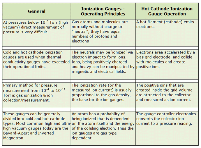
At vacuum pressures below 1.3×10⁻⁴ mbar (10-5 Torr), the direct measurement of pressure is difficult. Therefore, a specialty type of gauge is used for measuring very low-pressure ranges, typically from 10-10 to 1 mbar. In these ionization gauges, energized electrons will ionize residual gases and the resulting positive ions are then collected at an electrode and the current is converted to a pressure reading.
Due to their extreme calibration sensitivity to the gases in which they monitor, ionization gauges are often used under laboratory conditions. In fact, they are so sensitive that the use of a mass spectrometer is often necessary to determine the composition of the gas surrounding the gauge. There are two forms of ionization gauges, hot cathode, and cold cathode.
Cold Cathode Gauges
Operating ranges for cold cathode gauges are 10-2 to 10-7 mbar (7.5 x 10⁻³ to 7.5 x 10⁻⁸ Torr). While there exist several types of cold-cathode gauges (Fig. 5) including the Penning, the magnetron, the inverted magnetron, and the double inverted magnetron, all of them utilize a crossed electric and magnetic field to trap electrons. Since they have no heated filament, the electron discharge is initiated by stray field emission, that is, the magnetic field generated by the magnetization in a magnet. Since this process of electron discharge can take minutes to achieve at lower temperatures, cold cathode gauges are often turned on at high pressures (10-2 Torr or higher). Once activated, the magnetic field within the gauge will constrain the electrons in long path lengths that have a high probability of ionizing the residual gas. These ions are then collected and measured to calculate the pressure of the gas.
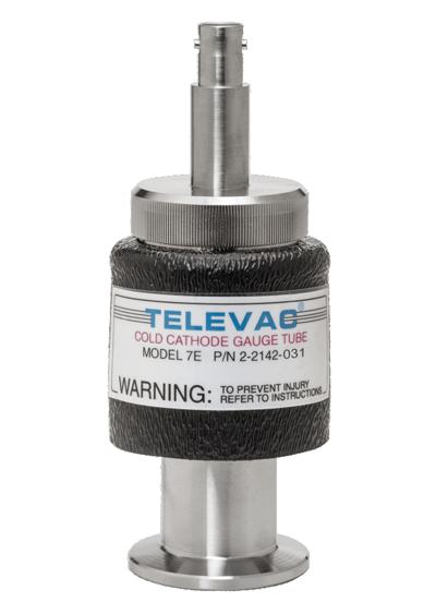
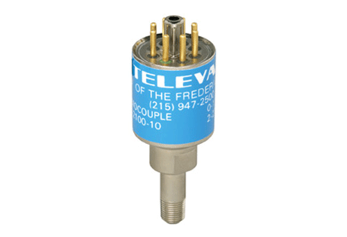
Special Notes About Cold Cathode Gauges (Fig. 5 & 6)
- Consider using Penning magnetron cold cathode technology where possible as it offers the greatest contamination resistant (over other designs, for example, those using inverted/double inverted magnetron cold cathode technology).
- Select cleanable cold cathodes for extended gauge life (bead blasting or abrasive pad cleaning). Simple gauge disassembly and cleaning for extended life and lower maintenance costs.
Nadcap Accreditation Note
To maintain Nadcap accreditation and comply with the requirements outlined in AMS 2769, rough vacuum gauges must be annually (once every year) calibrated to a NIST traceable standard, whereas high vacuum gauges (cold cathodes) require quarterly (once every 3 months) calibration. Active gauges greatly simplify this process by allowing you to return an individual active gauge for calibration without removing any cabling or other equipment from the vacuum system.
Pressure Ranges
The correct choice of gauge depends on knowledge of the working principles of the gauge, the range of pressures it can measure, and its accuracy over the required range. These factors have been determined by experience and there is a vacuum gauge for every pressure range.
- For low vacuum ranges (higher pressures) between atmospheric and 10 torr, Bourdon tubes, bellows, active strain gauges, and capacitance sensors are all suitable measurement devices.
- For mid-range vacuum requirements, those in the 10+1 torr to 10-3 torr range there are several choices including the capacitance manometer, a good choice for more accurate measurements or the thermocouple or Pirani type gauges.
- For a high vacuum, from 10-3 torr to 10-6 torr, either a cold cathode or Bayard-Alpert hot cathode gauges are used. There is some concern over accuracy and/or stability, and both require frequent calibration.
Gauge Location
Finally, a number of factors must be considered when installing the devices discussed above. In particular, the selection of the location for installation needs to:
- Avoid vacuum gradients
- Negate pumping effects
- Avoid strong magnetic and electrical fields
- Avoid contamination from product evaporation or oil vapors from diffusion or mechanical pumps.
Transmitters measuring sensor output, control units and cables must be properly matched to the device.
The Bottom Line
The secret to success is having accurate and repeatable gauges so as to ensure that the process being run remains under control and that the calibration procedures are simple and routine.
Hot Cathode Gauges
Operating ranges for hot cathode gauges are 10-3 to 10-10 mbar (7.5 x 10⁻⁴ to 7.5 x 10⁻¹¹ Torr). A hot cathode gauge (Fig. 7, Table 2) is comprised of a glass vessel with a heating element contained within that a gas of unknown pressure is introduced. Free electrons are discharged from the hot filament (typically tungsten), which supplies electrons at a constant controlled rate. These electrons are present within the bulk metal and are able to roam free allowing the material to conduct electricity. When the filament is heated, the energy introduced to these electrons allows them the ability to leave the metal’s surface and into the glass vessel of the gauge. The pressure of the gas is found by measuring the electrical current flowing between the anode and a cathode within the glass bulb. This current is proportional to the number of ions per unit volume, which is also proportional to the pressure of the gas.
Hot cathode gauges with a very high cathode temperature are known to produce errors and therefore the electrodes must be properly treated before use to minimize these risks. To eliminate such issues, the use of a cold cathode gauge might be more effective for vacuum measurement.
Summary
The intent of this article was not to cover all types of vacuum gauges but to point out the ones that are most often found on vacuum furnaces running heat treatment processes. References 1 – 5 contain more detailed descriptions of all types of gauges and the principles behind them.
References
- Brunner Jr., William F., Practical Vacuum Techniques, Robert E. Krieger Publishing Company, Inc., 1965.
- Bishop, Charles A., Vacuum Deposition Onto Webs, Films and Foils, 3rd Edition, William Andrew, 2015.
- Berman, A., Total Pressure Measurements in Vacuum Technology, Academic Press, 2014.
- Herring, Daniel, Vacuum Heat Treatment, BNP Media Group, 2012.
- Harris, Nigel, Modern Vacuum Practice, McGraw-Hill Book Company Europe, 1989.
- Kurt J. Lesker Company (www.lesker.com), Pressure Measurement Technical Notes, 1996 – 2019.
- Instruments Today (www.InstrumentationToday.com)
- Li, Yulin and X. Liu, “Vacuum Science and Technology for Accelerator Vacuum Systems”, Cornell Laboratory presentation.
- Stanford Research Systems (www.thinksrs.com), “SRS Manual, IGC100 Ion Gauge controller, Bayard-Alpert Ionization Gauges, Appendix A”
- Tring, Howard “Vacuum Gauges Used on Vacuum Furnaces”, Vac-Aero International, March 14, 2013
- 11. The Fredricks Company (https://www.frederickscompany.com/televac-vacuum-measurement/)
