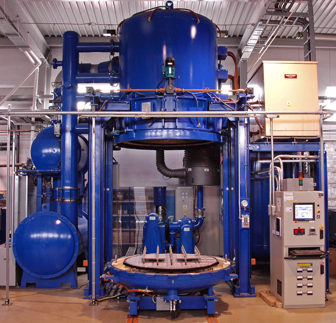
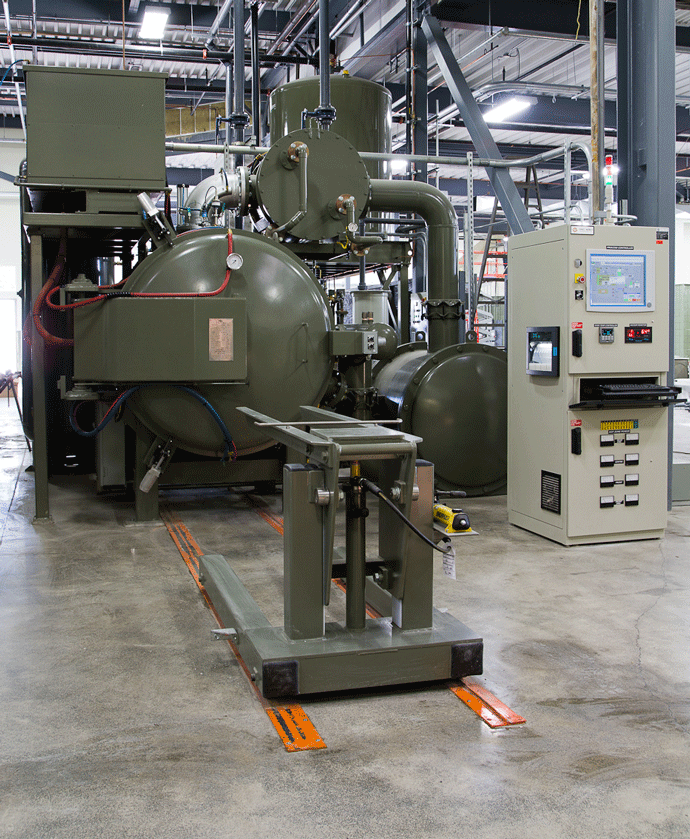
Vacuum furnaces are available in both batch and (perhaps less common) continuous styles with the vast majority of furnaces in use categorized as either vertical (Fig. 1a) or horizontal (Fig. 1b) in orientation. In this two-part article, we will discuss the uses and features of batch vacuum furnaces and provide an introduction to continuous furnace design.
Why Use Vacuum?
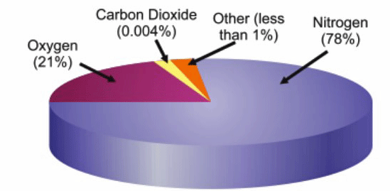
Let’s briefly review why vacuum technology is so important for heat treatment. The primary reason has to do with air and the reactive constituents contained within it. Air is a gaseous mixture that contains varying amounts of water vapor, oxygen, carbon dioxide, nitrogen and hydrogen (Fig 2) and each of these constituents of air are reactive with various metals. At room temperature these chemical reactions occur too slowly to be problematic, however, these reactions are greatly accelerated at the elevated temperatures required for heat treatment. There are changes to the microstructure of a material’s surface when a heated metal is exposed to air. The changes experienced can be either surface contamination or a thin exterior layer that is harder or softer than the interior of the part being heat treated. For example, a piece of steel will discolor when heated above about 200°C (392°F), forming a thin layer of ferrous oxide. This presents a challenge when heat treatment is necessary for applications where part cleanliness or appearance is important.
One solution to this problem is removing the air from within the furnace chamber prior to heat treating thus eliminating the source of any contamination. This is the underlying principle behind vacuum furnace technology. At the end of the vacuum process, an inert gas such as nitrogen, helium, argon or a gas mixture, is injected into the furnace’s heating chamber under high pressure to cool the load prior to opening the door.
Industries Served by Batch Vacuum Furnaces
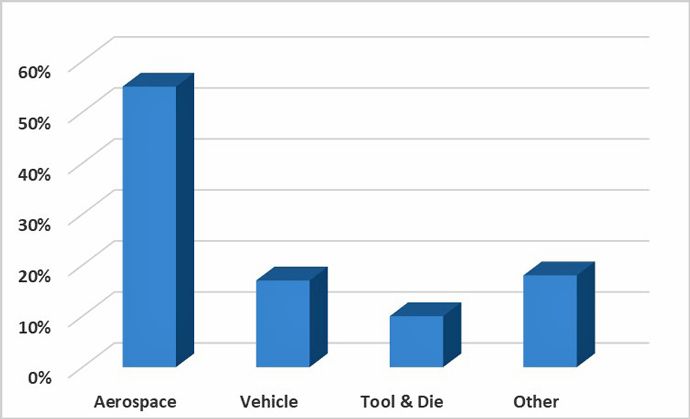
Batch vacuum furnaces are used in virtually every industry but are predominately used in the aerospace, automotive, and tool & die manufacturing industries (Fig. 3). Parts heat treated in vacuum furnaces include (by industry):
1. Aerospace – jet engine components, sensors, gears, honeycomb material, hydraulic system parts, airframe components, high strength titanium parts.
2. Vehicular and Marine – steering and suspension parts, transmission pinions, gears, and other components, catalytic converter cores, camshafts, timing gears, diesel injectors.
3. Tool and Die – tools, dies, punches, cutting tools, drills.
4. Communications and Electronics– satellites, semiconductors, heat exchangers, lithium batteries.
5. Energy – nuclear reactor equipment, fasteners, pump components.
6. Fasteners – construction bolts, miniature high-performance medical screws, superalloy bolts for nuclear reactors.
7. Food processing machinery – blades, cutters, gears.
8. Household items – sporting equipment, hand tools, silverware, scissors, knives.
9. Medical & Dental – parts for hip, knee and other joint replacement, surgical instruments, dental implants, orthodontic braces, and retainers.
10. Military and personal defense – triggers and other components for rifles and handguns, rockets and missiles, naval propulsion systems.
11. Power transmission – shafts, sprockets, gears, and pinions.
12. Commercial heat treatment – all of the above.
Applications Performed in Batch Vacuum Furnaces
Batch style vacuum furnaces are used wherever product quality is critical. Here are a few of the more common processes performed in batch vacuum furnaces.
Vacuum Brazing Under Vacuum
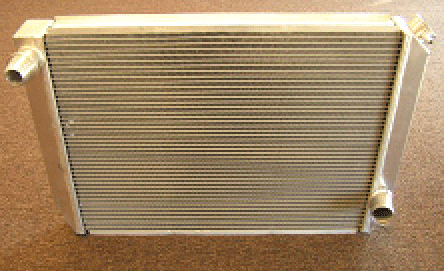
One of the most common uses of batch vacuum furnaces is vacuum brazing which is defined as a joining process, performed under vacuum, which melts a filler metal (called a brazing alloy) that joins two or more metal parts. Advantages of vacuum brazing include high joint strength, minimal alteration of the base material properties (in comparison to welding), no flux residue, joining of dissimilar metals, minimal residual stresses, and high-quality joints with no voids. The process can be used to join nickel, copper, ceramic to metal, and is frequently employed in the manufacture of radiators (Fig. 4) and oil coolers.
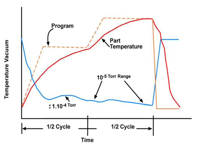
The quality of brazed connections depends greatly on the heating time and temperature, with the alloying and wetting action of the filler metal increasing with increased furnace temperature. The filler material must have a melting point lower than the substrate metals because it needs to be melted before it can flow into the joint by capillary action. In general, the lowest successful brazing temperature is preferred. The filler melting point is the primary, but not the only, factor to be considered when determining the furnace temperature. A lower furnace temperature minimizes heat growth and potential distortion, reduces chemical interactions between the base and filler materials, and maximizes the life of the fixturing. In addition to minimizing the temperature, the heating time (Fig 5) is also kept as short as possible. This has some of the same advantages as reduced temperature and also reduces operating costs.
In order to achieve a high-quality joint, the parts must be carefully fitted to minimize the gap between them. The substrate metals are typically prepared using chemical or abrasive cleaning as they must be uncontaminated and oxide-free. In the case of abrasive cleaning, a specific surface roughness must be achieved to allow the capillary action of the filler material to properly occur. In vacuum aluminum brazing, magnesium is used as an additive to the filler metal or the base metal, and this serves two purposes. After it starts to vaporize at approximately around 570°C (1058°F), the magnesium attracts oxygen and water vapor, serving as a getter material, which increases the purity of the environment in the furnace and provides a better joint. The magnesium additive also lessens the alumina oxide on the surface of the aluminum, improving adhesion between the filler and joint surfaces.
Vacuum Hardening
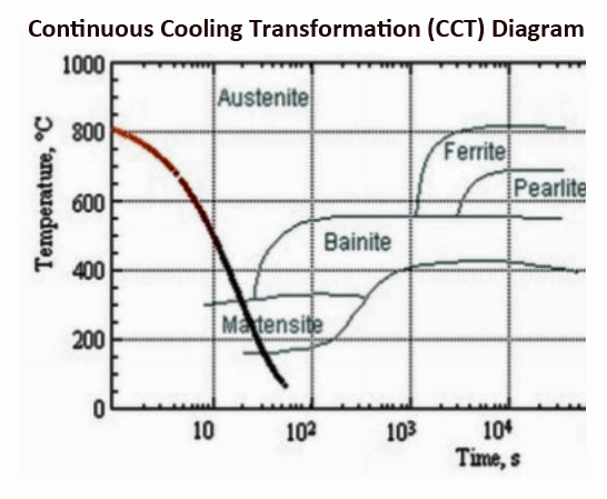
Another common process for batch vacuum furnaces is vacuum hardening. Steel and its alloys are not hard enough for many uses until they are hardened. The types of steel most commonly vacuum hardened are tool steels containing chromium, tungsten, molybdenum, and high speed and hot worked steel alloys. Hardening steel in a vacuum furnace consists of heating the parts to the austenitic range and rapid quenching in oil or a high-pressure inert gas. The choice of quenchant is determined by the metallurgy of the steel and the shape and application of the material being hardened. In order for hardening to occur, the steel must first be heated to its hardening temperature, as determined from the equilibrium diagram. At this point, it is in the austenite phase. The quick cooling during quenching causes the structure of the steel to change from austenite to a very hard state referred to as martensite (Fig. 6). In the martensitic state, the steel has a needle-shaped (aka acicular) grain structure.
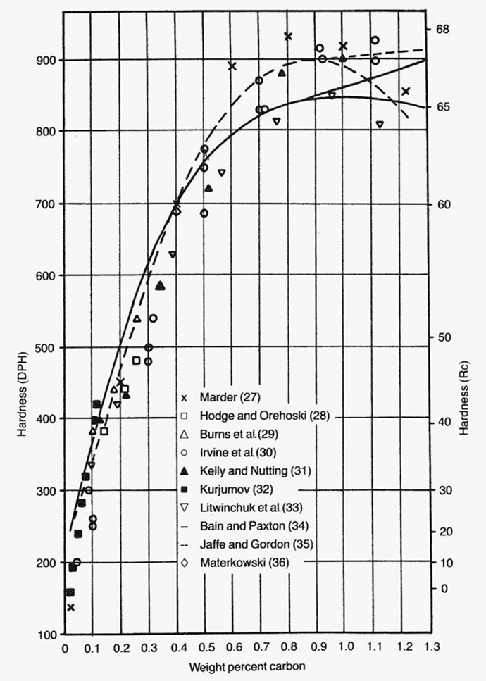
Steel requires at least 0.3% carbon to be successfully hardened, and the hardest steel occurs at approximately 0.9% (Fig. 7). In order to provide a successful quench, the cooling must be fast enough that the carbon atoms in the steel do not have time to diffuse out of the crystal structure in sufficient quantities. If the cooling is not rapid enough, the steel will transform from austenite to the much softer ferrite, and result in a failed process.
The quenching process produces brittle steel and generates thermal stresses due to uneven cooling and residual stresses due to variations in the grain structure. The variations in cooling speed between the outer and inner material layers result in more martensite in the outer layers of the part than the interior. The steel crystals in the martensitic state are slightly larger than the austenitic. The outer martensitic layers, therefore, are under stress as they are prevented from growing because the interior austenitic crystals do not enlarge to the same extent. In order to mitigate this stress, tempering is necessary.
Tempering Steel in a Vacuum Furnace
Hardening is typically followed by tempering since the as-quenched material is brittle and lacks toughness and ductility. Vacuum furnaces operate using radiant heat transfer, whereby heat energy is transferred directly from the heating elements to the work, without an intermediate gas. Radiant heat transfer is most effective above approximately 650°C (1,200°F), but steel is usually tempered at temperatures below 600°C (1,112°F). Tempering in a vacuum should be performed using a convection fan option so as to achieve a temperature uniformity of ± 6ºC (± 10ºF) or better. Without this feature, one may not be able to achieve the consistency of temperature needed to ensure that parts are properly tempered.
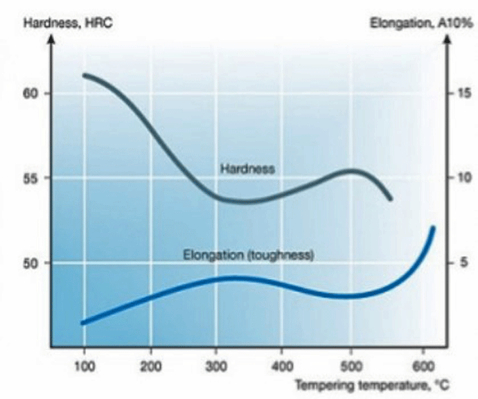
Tempering quenched steel at temperatures between 66°C and 148°C (151°F and 298°F) has minimal effect, other than slight stress relief. Tempering between 148°C and 205°C (298°F and 401°F), will result in significant stress relief and a reduction in hardness (Fig. 8). Materials requiring more hardness than toughness, such as tool steels, are typically not tempered above 205°C (401°F). Rather, the tempering time is varied to provide the desired hardness. Tempering from 260°C to 340°C (500°F to 644 °F) causes a reduction in ductility and an increase in brittleness. This is called the tempered martensite embrittlement (TME) range, and it is normally avoided. When greater toughness is necessary, higher tempering temperatures of 370°C to 540°C (698°F to 1,004°F), are utilized, although this comes at the expense of strength. Tempering at yet higher temperatures, between 540°C and 600°C (1,004°F and 1,112°F), will produce even greater toughness, but at a significant reduction in strength and hardness. If steel is heated above 600°C (1,112°F) for too long, it can experience yet another stage of embrittlement, called temper embrittlement (TE). In this range, steel is heated only briefly and must be quickly cooled to avoid temper embrittlement.
Summary
All manufactured parts will benefit from vacuum processing and the number of applications in which vacuum technology is being used is virtually unlimited. Batch vacuum furnaces dominate the landscape and equipped with either high gas pressure quenching or oil quenching offer the industry tremendous flexibility with respect to processing all types, sizes, and materials.
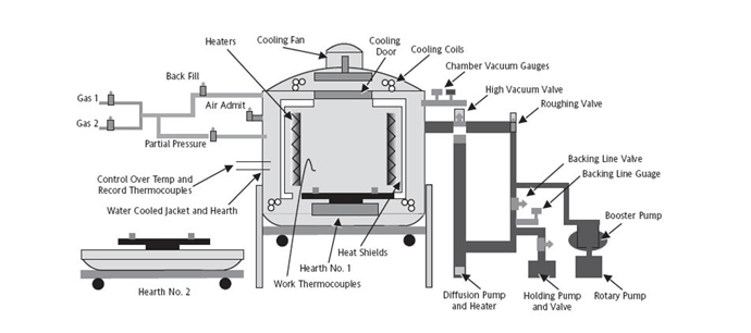
In the following section, we will introduce the major components of a typical batch furnace, and then take a brief look at how continuous vacuum furnaces differ from them. In the article above, we looked at the reasons vacuum technology is important to the thermal processing industry and discussed a few of the most common applications for vacuum furnaces. In the following section, we will talk about the major components of a batch vacuum furnace and briefly consider continuous (aka semi-continuous) vacuum furnaces. Batch vacuum furnaces are made up of various subsystems (Fig. 9): vacuum pumps; a hot zone complete with a heating source, insulation, hearth/load support structure; vessel or shell with structural support system; power components; and instrumentation.
Vacuum Pump System
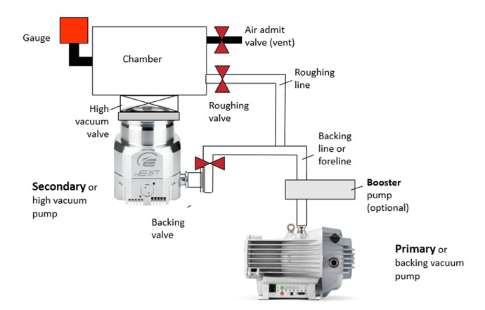
The purpose of vacuum pumps and the related components is to remove the air from the heating chamber. Although the vacuum pumping system does not remove all the air, the goal is to remove enough of the remaining air so that any oxygen present will not react with the material being processed in the furnace. There are two categories of pumps employed on typical vacuum furnaces: a primary pump with or without an optional booster pump (aka blower) and an optional secondary diffusion pump (Fig. 10).
For most batch vacuum systems, a combination of a mechanical pump (i.e., wet or dry pump) and booster pump will reduce the pressure to roughly 10-3 mbar (millibar) which is considered a medium to high vacuum. For reference, 1 bar is atmospheric pressure, whereas a millibar is 1 thousandth (0.001) of current atmospheric pressure. Therefore, 10-3 mbar is 1 millionth (0.000001) of atmospheric pressure. The primary pump is used for the initial pump-down from atmospheric pressure via the opening of a roughing valve. When the efficiency of the primary pump or primary pump plus booster pump drops off, the roughing valve is then closed and the poppet valve is opened to the secondary (diffusion) pump. The secondary pump is designed to reduce the pressure to very high or ultra-high vacuum, as low as 10-10 mbar.
A vacuum furnace using only a primary pump will remove enough air to prevent surface reactions (i.e. discoloration) when heat treating typical stainless steels or tool steels. However, more reactive metals like titanium and many superalloys require very high vacuum levels and therefore a secondary pump (most commonly an oil diffusion pump) is necessary. Diffusion pumps are recommended for many vacuum brazing applications and are considered an important accessory for most batch vacuum furnaces (or at least a port for the future addition of a diffusion pump).
Hot Zone
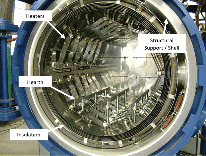
The vacuum furnace hot zone consists of four subsystems: the insulation system, the heating elements, the hearth/load support system, and the structural shell that surrounds and supports the furnace (Fig. 11). In most cases, the hot zone, by design, is removable from the vacuum chamber for maintenance, repair or replacement. Since the design of the hot zone greatly influences the equipment’s performance, various material choices (all metal, all graphite, combination) and construction methods are selected for different temperature ranges and applications.
Insulation
The hot zone insulation system is designed to minimize the heat transfer through the furnace wall and keep the heat inside the furnace. Since vacuum furnaces operate at temperatures up to 3000°C (5400°F), the insulation system is very carefully engineered to reduce heat loss by all three modes of heat transfer (radiation, conduction, and convection).
There are several insulating system designs common in vacuum furnaces: all-metal insulation, all-graphite insulation, and composite designs integrating both metal and graphite. The all-metal insulation system utilizes several layers of heat shielding, with air gaps between each layer (Fig. 12). Each layer serves to reduce radiant heat transfer with each shield having a cumulative effect. A common shield arrangement for a furnace rated at 1315ºC (2400ºF) is two molybdenum shields backed by four stainless steel shields.
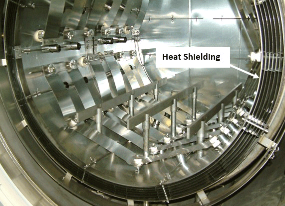
Due to its high-temperature resistance, graphite insulation is often utilized in furnace construction. A typical graphite insulation system employs 38 – 50 mm (1.5 – 2.0 inches) of insulating graphite board or blanket material, with an inner layer of graphite foil or foil-bonded carbon composite, for reduced emissivity (increased reflectivity) of the radiant heat. Graphite insulation offers superior insulating properties and is typically less expensive than all-metal hot zones. However, graphite carries a slightly higher risk of heat zone contamination due to trapped gases such as water vapor within the insulation, as well as possible outgassing or breakdown of the graphite.
Heating System
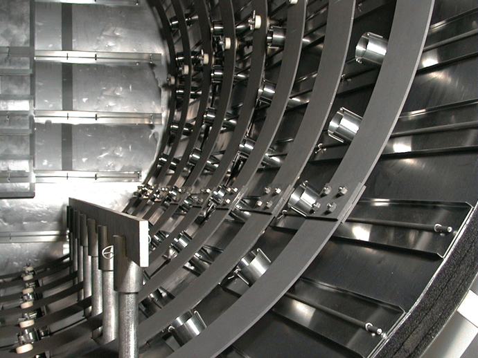
Vacuum furnaces are almost exclusively heated with electric resistance type elements. The choice of electric heaters is based on the furnace’s maximum operating temperature. Nickel-chromium alloyed heaters are typically utilized at low temperatures, and graphite or molybdenum varieties are employed in higher temperature applications like hardening or brazing. Tantalum and graphite are used in applications above 1482°C (2700°F) since they have a higher melting point and better corrosion resistance. In the past, molybdenum was the most common element material, but this changed as graphite technology improved making graphite a popular option today. The heaters are typically mounted in a 360° octagonal arrangement or curved strips (Fig. 13) that fully surround the load to provide good temperature uniformity.
Hearth/Load Support System
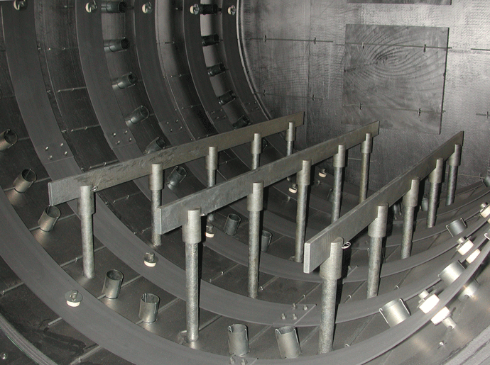
The furnace hearth consists of multiple support rails that are mounted parallel to the furnace length, with spaces in between to allow clearance for loading via fork truck or other means (Fig. 14). Posts through the furnace floor support the weight of the load, transferring it to the exterior furnace structure below. Vacuum furnace hearths are most commonly made of graphite or molybdenum.
In the graphite design, the hearth rails are often slotted on top to contain molybdenum or ceramic rod inserts. This minimizes the possibility of load contact reactions such as eutectic melting, which is the localized melting of the load in the area of contact with the graphite. Other solid-state diffusion reactions are also avoided.
Molybdenum has a higher strength than graphite. Therefore, a molybdenum hearth can be lighter than a graphite hearth rated for the same load weight. This allows for faster furnace heating and reduces the heat input required. However, graphite hearth rails are generally less expensive than molybdenum but less durable. There are new, more expensive graphite hearth materials available that have greatly improved durability, but their cost can exceed that of molybdenum. Molybdenum is susceptible to warping after repeated heating, is brittle and can be damaged by a sudden impact. It must occasionally (and very carefully) be hot straightened. Graphite hearths do not have this drawback and will maintain their shape over time.
Furnace Structural Support System
Vacuum furnaces utilize an exterior shell, usually cylindrical, that supports the insulation system, load hearth, and heating elements. This shell can either be plain carbon steel, stainless steel or, in some cases, aluminum. The cylindrical design is more common than rectangular due to its inherent strength in resisting the pressure of the atmosphere on the shell exterior while the equipment is under vacuum. A vacuum furnace experiences tens of thousands of kilograms of collapsing force while under vacuum. A double wall construction, with an annular spacing of 25 – 38 mm (1 – 1.5 inches) is common so that a coolant (water or a water/ethylene glycol mixture) can be circulated between the interior and exterior walls of the shell. The cylindrical shape takes advantage of the same principle used in dam design (Fig. 15), whereby the dam wall is arched so the water pressure exerts a compressive force to the wall as it transmits the force to the foundation or abutments.

Vacuum Furnace Power and Instrumentation Control System
A vacuum furnace control system uses a closed-loop controller in conjunction with SCR power controllers to provide PID (proportional, integral, derivative) control of the furnace temperature. In addition to temperature, the furnace control system must also control the machine functions such as vacuum, backfill gas control, and shell cooling. A hybrid controller or PLC is commonly used for this. More advanced furnaces incorporate a supervisory control and data acquisition (SCADA) system to record temperatures, collect maintenance and alarm data, and provide recipe storage. This type of system typically incorporates a large color touchscreen operator interface (Fig. 16) designed for use in a factory environment.
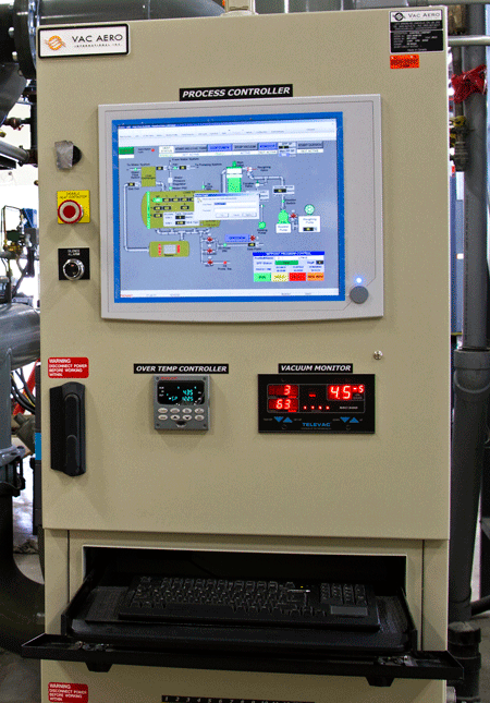
The system is often connected to the company’s network to make process information accessible to operators and engineers throughout the organization. A modem can be included to allow remote offsite problem diagnosis or debugging by equipment vendors. The systems can also be designed to send an email in the event of an alarm condition or end of a cycle.
Continuous Vacuum Furnaces
Although the majority of vacuum furnaces utilize a batch configuration, for some applications a continuous design can be advantageous. Continuous vacuum furnaces function in a semi-continuous manner where the load is processed through multiple heating zones sequentially and commonly utilize a pusher system to move the load from one chamber to the next. The continuous vacuum furnace consists of different modules connected in an in-line manner: the load module, heating module(s), cooling or quench module, and unload module. Each module is separated from the others by a vacuum-sealed door.
The first module (called the load module) accepts the incoming cold load. After the door closes, a vacuum is drawn on the load module while it contains the unheated load. Next, the load is transferred from the load module into the heating module(s) for the heating process to be performed. Typical continuous furnaces utilize from one to six heating modules. The heating modules are put under vacuum prior to the load entering, so the load is not exposed to the factory atmosphere during the transfer.
After being processed through the heating modules, the load enters the unload module, which works similar to the load module by using an intermediate door to isolate it from the heating modules. Some furnaces incorporate an oil or gas quench prior to the load entering the unload module, providing similar quenching capabilities to a batch furnace. Another design cools the load in a cooling module while maintaining vacuum. In this design, a water-cooling jacket cools the shell of the cooling module, and the load releases its heat via radiant heat loss.
Due to the material handling systems and the multiple modules required, continuous vacuum furnaces carry a higher price tag than batch designs but can offer higher throughput productivity. These costs and complexities can only be justified if running large quantities of identical or similarly sized parts. Continuous vacuum furnaces are not economical in small or medium lot production lines due to the high capital requirement and large footprint. In addition, the user is vulnerable to downtime in the event of equipment failure or maintenance. This is in contrast to a scenario where several batch furnaces are incorporated to handle the same load volume, and failure of one furnace does not bring the entire heat treat line to a halt. Some applications for continuous vacuum furnaces include hardening of high-speed steel, sintering and low pressure carburizing.
Summary
Whether your choice is a batch or continuous style furnace, knowing the various features of the design, their advantages and limitations are critical to successful operation. Each design requires its own unique maintenance requirements so the ultimate decision should be based on application and productivity.
References:
- Vac-Aero International (https://vacaero.com)
- Learn Hive (http://www.learnhive.net)
- Chart generated by the author – data from Technavio (https://www.technavio.com/), 2012.
- API Technologies (http://micro.apitech.com/default.aspx)
- California Brazing (https://www.californiabrazing.com)
- G. Krauss. Martensitic Transformation, Structure, and Properties in Hardenable Steels, in Hardenability Concepts with Applications to Steel, D.V. Doane and J.S. Kirkaldy, eds., AIME, Warrendale, PA, 1978, pp. 229-248.
- Naman M. Dave Assistant Professor, Mechanical Eng. Dept. Gandhinagar Institute of Technology. Material Science & Metallurgy 2131904 Chapter 8 Heat Treatment.
- Callister Jr., William D., and David G. Rethwisch. Material Science and Engineering, an Introduction. 1985.
- Edwards Vacuum (https://www.edwardsvacuum.com)
- Wikipedia (www.wikipedia.org)
