Heating element design and selection is critical to the proper functioning of any vacuum furnace and is dependent on a number of factors: maximum operating temperature; power load; partial pressure and quench gases and life expectancy. The vast majority of vacuum furnaces are electrically heated. As such, heating elements are constructed of either high-temperature metallic alloys such as stainless steel, nickel-chromium, molybdenum, tungsten, tantalum, or of non-metallic materials such as graphite and silicon carbide.
Stainless steel and nickel-chromium alloys are commonly used for lower temperature applications such as aluminum brazing and at higher partial pressures, while graphite, molybdenum and tungsten are more common for higher temperature processes such as hardening, sintering and nickel or copper brazing. Since the heating elements create the heat and transfer it to the load, the importance of choosing the proper alloy for its construction is critical in maximizing the heating element’s longevity, reliability, efficiency, and ultimately the process results. The different heating element types, as well as their advantages and limitations, are discussed here.
Resistance Heating Fundamentals
Let’s take a moment to review the basics of resistance heating and how it impacts the furnace heating element design and selection. Electric heating is fundamentally the conversion of electrical energy to thermal energy. It is based on the principle that the heating element material resists the flow of electricity, generating heat in the process. At the atomic level, a voltage difference between the ends of a conductor (i.e. the resistance heating element) creates an electric field that accelerates the electrons through the heating element in the direction of the electric field, which gives off kinetic energy. While being drawn through the material by the electric potential, the electrons collide with the atoms that make up the heating element. Every time an electron strikes an atom, it transfers some of its kinetic energy (in the form of heat) to that atom. The cumulative effect of all these collisions results in the electricity being converted to heat in a process referred to as Joule (or resistive) heating. Despite their small size, the number of electrons passing through a material per second (at a current of one (1) ampere) is a staggering 6.25 x 10¹⁸. For comparison the number of grains of sand on all the world’s beaches is estimated to be roughly 7.5 x 10¹⁸. The result of this mass movement of electrons is the generation of useful heat energy.
There is a formula that calculates the power generated from a resistance heating element (Equation 1):
(1) P = I2 x R
where:
P = Power (watts),
I = Current (amperes)
R = Resistance (ohms)
Note that the power generated is proportional to the square of the current, meaning that the power is more sensitive to changes in current than resistance. Therefore, at a constant voltage, the effect of a change in current overwhelms the effect of the corresponding change in resistance. In practice, decreasing the resistance causes the current to increase, which in turn increases power by a greater factor. Thus, at a constant voltage, the net effect of decreasing resistance is to increase power consumption and heat generation.
Heating Element Selection and Material
The objective in selecting heating elements is to choose a material and cross-section that provides the proper electrical resistance to generate the desired heat output. In addition to the resistivity (a property of the heating element material), the cross-sectional area of the material determines its resistance. Everything else being equal, the larger the cross-section, the lower the resistance. As a result, heating elements for low power applications are thin ribbons of material. For higher heat output applications, the thickness of the elements increases, which lowers its resistance and allows more electric current to flow. For vacuum furnaces, the heating elements are typically wide strips and ribbon-shaped to maximize both their physical and radiant surface areas.
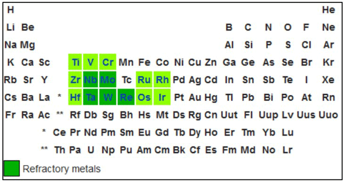
Metallic heating elements for high-temperature vacuum furnaces are commonly made of refractory metals (Fig. 1). Refractory metals are extremely high melting point metals that are resistant to wear, corrosion, and deformation. Examples are molybdenum, tungsten, and tantalum, of which molybdenum is the most commonly used in vacuum furnaces due to its cost. Molybdenum undergoes a significant (five times) increase in resistivity when heated to typical operating temperatures, because of this, the electrical control system must compensate for this as the operating temperature increases. Tungsten heating elements can be used at higher operating temperatures but are more expensive. Graphite is less costly than metallic elements and in addition, undergoes a 20% decrease in electrical resistance when heated.
Tantalum and graphite are used in applications above roughly 1482°C (2700°F) due to their higher melting point and resistance to corrosion. Years ago, most heating elements for vacuum furnaces were made of molybdenum, as early graphite heating element designs were bulky, with limited configurations offered, and they were susceptible to failure at the electrical connections. There was also a concern that contaminants could leach out of the graphite and reactive unfavorably with certain metals being processed in the furnace. These challenges with graphite heating elements have been overcome, and today graphite is a well-accepted choice for heating element material.
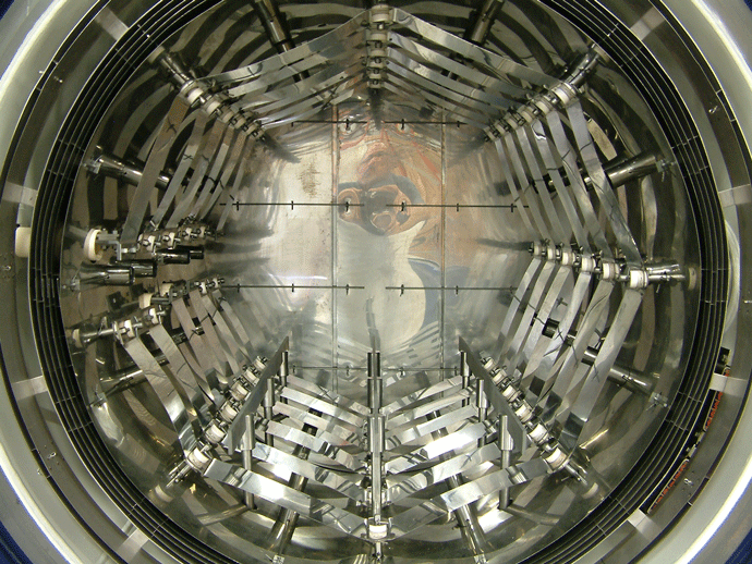
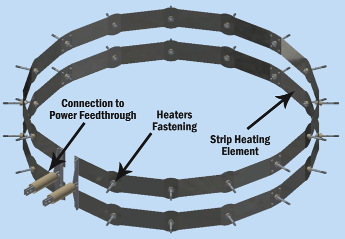
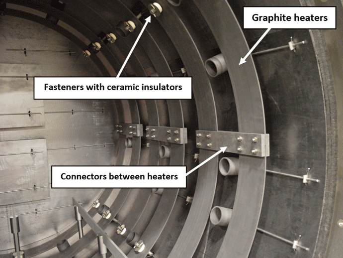
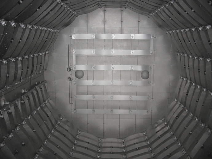
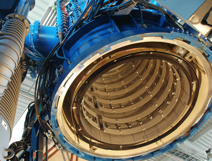
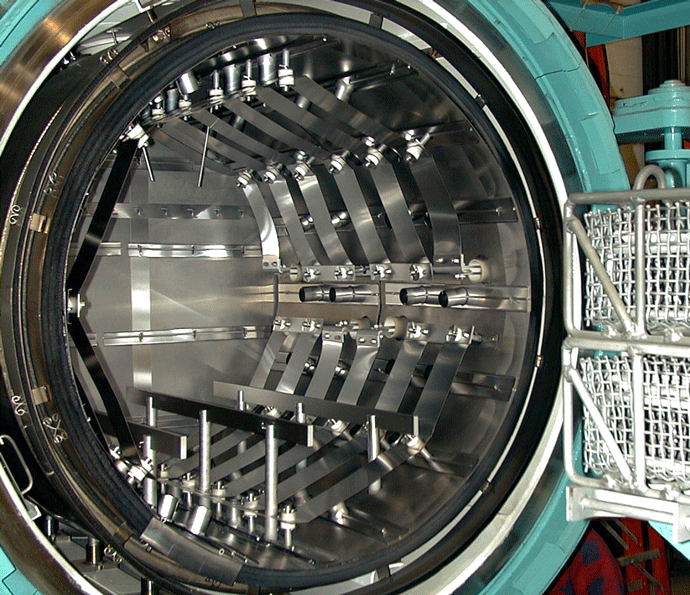
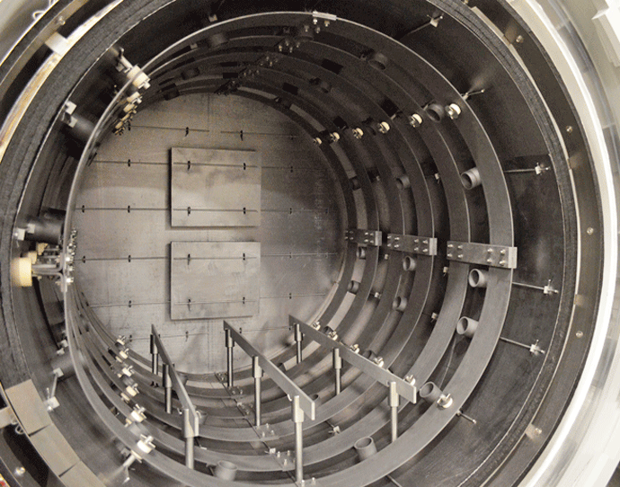
Graphite heating elements are commonly arranged in 360° circular (Fig. 2) or octagonal (Fig. 3) configurations but are also in supplied tubular or flat strip form primarily for rectangular hot zone designs. All graphite elements are easy to install and offer excellent temperature uniformity. In order to reduce the chances of arcing and short circuits, vacuum furnace heating systems typically operate at low voltages of 70 volts or less. The total furnace heat output commonly ranges from 40 to 300 kW. Since the heating elements transfer heat by radiation to the interior of the furnace and to the load, the heating element surface temperature is always higher than the furnace process temperature. The difference can range from a few degrees during soak to several hundred degrees during the furnace heat-up, depending on the process requirements and the heating element design. In practice and to provide a safety factor against failure, the maximum furnace temperature is limited to within roughly 50°C (90°F) of the maximum temperature the heating element material can withstand.
Why Does Vapor Pressure Matter?
When evaluating the material to be used as a resistance heating element in a vacuum, it is useful to understand vapor pressure and evaporation. With respect to evaporation, we intuitively think of a liquid evaporating into a gas, as water does when heated. We certainly wouldn’t expect metals or other solid material to evaporate. In actuality, there are molecules continually leaving every solid material, even at room temperature and pressure, and forming a thin layer of vapor around the material. Some of these molecules then condense back onto the material and return to a solid state. Above a certain pressure in a closed container (referred to as the material’s vapor pressure) the rate of evaporation equals its rate of condensation (Fig. 4) and there is no net loss of the material, resulting in a state of equilibrium.
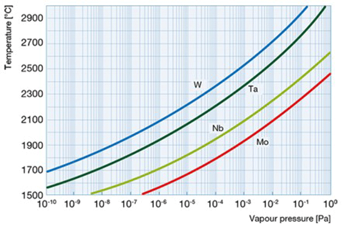
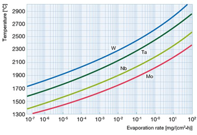
When a material is placed in a vacuum chamber and the pressure is reduced below its vapor pressure, the material evaporates continuously. The resulting vapor is carried away by the pumps or condenses elsewhere in the vacuum furnace. If this happens to a heating element, the result will be a reduction in cross-sectional area resulting in burnout of the heating element. This evaporation rate accelerates at elevated temperatures (Fig. 5). In order to prevent this type of failure, heating elements must be made of a material that has a lower vapor pressure than the pressure at which it will be operated in the furnace. In addition, partial pressure atmospheres can be used above the critical evaporation temperature of the element material selected.
Mounting and Wiring of Heating Elements
Heating elements are held in place to the furnace shell using ceramic or quartz insulators (Fig. 6). Ceramics provide excellent electrical isolation of the heating element circuit, but the insulators must be kept clean as they are vulnerable to short-circuiting if covered with carbon dust or metallic condensates (aka metalized) from the process or from graphite insulation, the part fixtures, the hearth, or contaminants present on the workload. Often ceramic insulators can be cleaned by removing them from the furnace and heating them, in air, in a small laboratory furnace.
If the furnace is operated at too low a vapor pressure, metals such as copper and chromium in the process load can volatize (evaporate) forming a vapor and subsequently condense on the element insulators. Since these metals are conductive, short-circuiting can result. Discoloration, often in the form of a blackish area or a “rainbow sheen” (as observed when holding a CD at a certain angle to the light). Care must be taken when performing such processes as low-pressure vacuum carburizing to avoid excessive soot buildup.
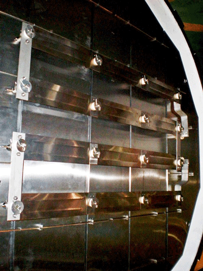
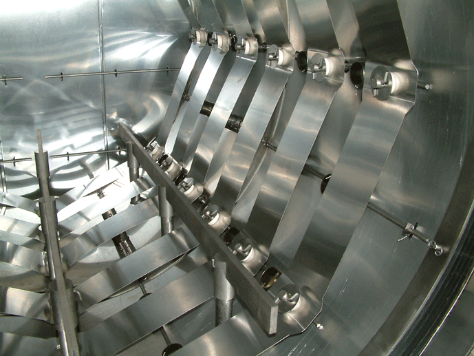
The individual graphite heating elements are usually connected with graphite bridges that are bolted in place to make the electrical connection from one element to the next. In addition to being radially mounted around the perimeter of the heating zone, on occasion heating elements are mounted on the rear wall (Fig. 7) or the door interior (Fig. 8). This helps improve temperature uniformity and results in improved temperature uniformity (e.g., aluminum brazing applications).
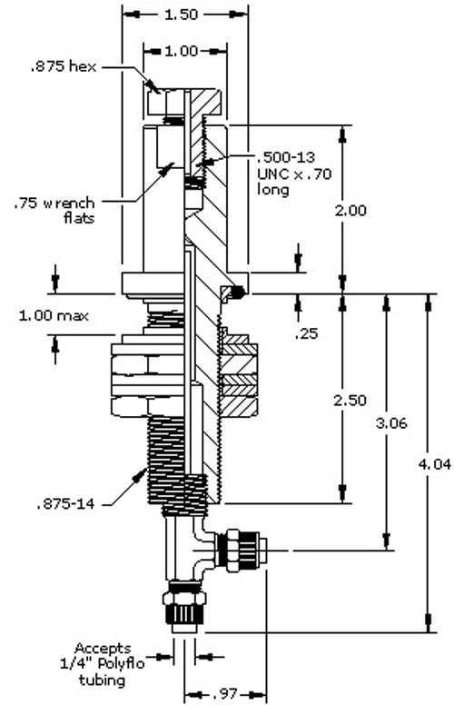
The electrical connection to the heating elements is accomplished via a water-cooled feed-through, which is a sealed connection containing the conductor that carries the current to the heating element. Feed-throughs are available in a variety of current ratings including high capacity designs (Fig. 9). Water-cooling prevents overheating. The cooling should be done via a closed-loop, grounded cooling system and non-conductive coolants (such as deionized water or ethylene glycol) to prevent the coolant from becoming part of the circuit. Cooling lines must be constructed of a nonconductive material such as polypropylene tubing.
Maintenance and Service Life
Maintenance is a critical aspect of proper vacuum furnace operation, especially in regard to the heating elements. After every load, the heating elements should be visually checked for damage and the heating element connections inspected for tightness. In the event of damaged elements, repair is sometimes possible. It might be possible to patch graphite heating elements or replace the damaged section with a new one. Molybdenum heating elements can be typically repaired up to three times per element band. This requires special precautions due to the brittleness of molybdenum and if heated during the repair, the toxic nature of molybdenum dioxide vapors (a yellowish smoke).
At a minimum of once a month, heating element resistance to grounding should be checked to ensure there are no shorts. This is especially important if the furnace performs low-pressure vacuum carburizing. An acceptable reading for most furnaces is 90 – 100 ohms. After many duty cycles, molybdenum elements and their insulators metalize and their resistance to grounding gradually drops. A measurement of 10 ohms or less typically indicates failure.
Summary
The selection and use of the proper heating element material and design help ensure that workloads are uniformly heated, and that tight temperature uniformity is maintained throughout the hot zone.
In the section above, we reviewed the fundamentals of resistance heating and discussed the most important factors affecting the design and selection of heating elements. In the following section, we will take a closer look at the various heating element materials, and compare their temperature ratings, cost, and suitability for different process applications.
Heating Element Materials
Heating element materials can be broadly divided into categories of metal, graphite, and silicon carbide (a semi-metallic material sometimes characterized as a ceramic). These materials have varying degrees of reactivity to oxygen in that some can tolerate elevated temperatures in the presence of oxygen while others must be protected from oxygen. The elements of tungsten, molybdenum, tantalum, and graphite all fall into the category of oxygen-sensitive materials. This is particularly important for the furnace owner to understand because even temporary exposure to oxygen can cause oxidation that will permanently impact the heating elements performance.
 Maximum Heating Element Temperature and Watt Density
Before beginning our comparison of heating element materials, let’s take a moment to point out that when rating the materials for maximum temperature, we are referring to the maximum element temperature, not the maximum furnace temperature. If the temperature of the heating element exceeds the maximum allowable temperature of the material from which it is made it can embrittle, decompose, or change phase – all of which can cause failures or reduce life expectancy. Because the heating elements transfer heat by radiation to the furnace interior and to the load, the element temperature is by definition higher than the temperature of the furnace or the load. Therefore, a heating element must be selected whose maximum temperature is safely higher than the required furnace or load temperature. This safety range is typically 50 – 200°C (122 – 392ºF) but can vary significantly depending on the heating rate, cycle time and other factors. Only heating element materials with a maximum temperature well above the furnace maximum temperature should be considered.
Maximum watt density of the heating element is another important consideration. It is also referred to as the power density or the watt loading and the units are heating element power divided by the surface area from which it radiates its heat. It generally ranges from 5 – 30 watts/cm2 (32 – 193 watts/in2). The power density is directly proportional to the heating element temperature, as a greater density of power on a certain heating element area will raise it to a higher temperature. The higher the maximum allowable temperature of the heating element material, the higher the maximum allowable watt loading will be and the longer the heating element life. Each material has a maximum allowable watt loading, above which it is susceptible to rapid deterioration. In order to use a lower watt density and provide extended heating element life, one strategy is to use a greater number of heating elements in the furnace, each with a lower watt density. In this way, the total furnace heat input can be achieved with less stress on each heating element. The added cost of these heating elements must be considered and weighed against the extended heating element life to be anticipated. Also, a greater number of elements requires more physical space, which may or may not be available in the furnace.
 Molybdenum
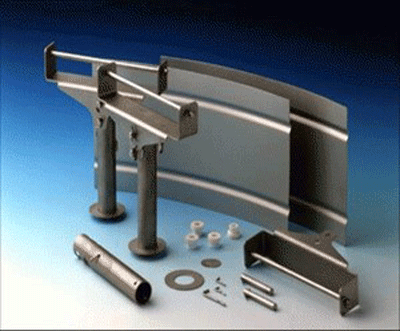
One of the most prevalent heating element materials for vacuum furnaces is molybdenum, a refractory metal. Molybdenum (Fig. 10) tolerates high temperatures, resists bending and cracking, and is a very good electrical conductor. It can be used up to 1700°C (3100°F), above which it becomes brittle and susceptible to physical damage. Molybdenum is commonly used in moderate temperature general heat treatment processes such as hardening and brazing (Fig. 11).
Molybdenum is very sensitive to contamination in the presence of oxygen and/or moisture, which causes failure due to dulling and the resulting change in emissivity. It is often alloyed with various materials (Table 1) to give it enhanced operating characteristics. The purity of molybdenum also affects its properties, and it is available in several grades. The material’s strength, ductility, and creep resistance are improved by adding various percentages of titanium, copper, zirconium, hafnium, carbon, rhenium, niobium, tantalum and yttrium, as well as oxides of the rare earth elements lanthanum, tungsten, and cerium. Molybdenum heating elements can be operated at a power density up to roughly 15 watts/cm2 (100 watts/in2) of element surface area.
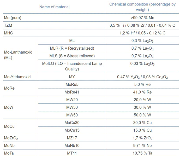
The most common choices of molybdenum material for heating elements are: pure molybdenum, TZM (molybdenum-titanium-zirconium), and MoLa (lanthanated molybdenum). Pure molybdenum is a popular choice as it offers a good balance of temperature resistance, strength, and affordability. It can be used at temperatures up to 1200ºC (2192°F) element temperature without risk of recrystallization. TZM is a material made by powder metallurgy techniques containing molybdenum, titanium, and zirconium with a limited number of very fine carbides. This alloy is stronger than pure molybdenum and has a higher crystallization temperature and resistance to creep at element temperatures up to 1400°C (2552°F).
By contrast, MHC (c.f., Table 1) is recommended for use up to a 1550°C (2822°F) element temperature. In addition, lanthanated molybdenum (MoLa) contains a fine array of lanthanum trioxide (up to 0.7%) particles that form a “stacked fiber” grain structure. This combination produces excellent resistance to recrystallization and high-temperature warpage. Lanthanated molybdenum is used up to a 2000°C (3632°F) element temperature.
Tungsten
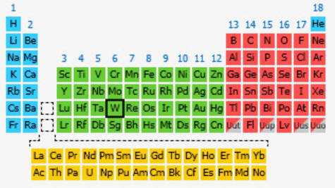
Tungsten has electrical, mechanical, and thermal properties similar to that of molybdenum, its neighbor on the periodic table (Fig. 12) while also having a much higher melting point. As a result, tungsten has the highest allowable operating temperature of the commercially available heating element materials. It retains its strength well at elevated temperatures and has good mechanical and thermal stability. Like molybdenum, tungsten is used in moderate temperature general heat treatment processes such as hardening and brazing. Tungsten heating elements are also utilized for higher temperature, specialized heat treatment processes.
Tungsten (Fig. 13) is less ductile than molybdenum and is therefore somewhat more difficult to form. It also has the same susceptibility to embrittlement, mechanical and thermal shock. Like molybdenum and the other oxygen sensitive materials, tungsten heating elements must not be allowed any exposure to air while at elevated temperatures since the material oxidizes in air starting around 500°C (932°F) and occurs rapidly above about 1200°C (2192°F). At a pressure of less than 10-2 torr, tungsten can be used up to 2000°C (3632°F) element temperature. At less than 10-4 torr, it is resistant to evaporation up to roughly 2400°C (4,352°F). To avoid embrittlement due to overheating, tungsten and molybdenum heating elements should be used with a ramping temperature control system that will limit the power applied during cold start-up conditions.
Graphite
Graphite heating elements are an increasingly popular choice in vacuum furnaces used for general heat treatment processes like hardening and brazing. Due to improvements in materials and manufacturing techniques, the use of graphite heating elements now exceeds that of molybdenum heating elements in these applications. Manufactured from various amorphous carbon compounds in a curved strip shape. This allows it to conform to the perimeter of the furnace hot zone (Fig. 14). Graphite elements have a lower thermal mass than previous generation graphite rod or bar elements. Graphite is unaffected by thermal shock and will not degrade due to frequent heating and cooling. Being moderately resistant to mechanical impact, graphite heating elements are more durable than their molybdenum counterparts while having better resistance to operational mishaps such as accidental breakage or braze alloy spill.
Graphite is oxygen sensitive and must not be exposed to air while at elevated temperatures. Oxidation in air starts around 500°C (932°F) and proceeds rapidly, experiencing up to a 1% loss of mass per day under certain conditions. After repeated exposure to air at elevated temperatures, the material will start to lose thickness, eventually resulting in structural failure. At pressures down to 10-2 torr, graphite can be used up to 2450°C (4442°F) element temperature. Further lowering the pressure to 10-4 torr, graphite is typically operated up to 2150°C (3902°F) element temperature.
To ensure mechanical stability, graphite heating elements are thicker than comparably-rated elements of other materials. Since the electrical resistance of any material decreases with increased cross-sectional area allowing for increased current flow, graphite heating elements must be run at reduced voltage and higher current to ensure proper power rating.
Nickel Chromium and Iron Aluminum Heating Elements
These metallic heating element materials are among the least costly and have the lowest operating temperatures of the heating elements used in vacuum furnaces. Nickel chromium and iron aluminum heating elements offer good resistant to mechanical and thermal stresses, and repeated thermal cycling is not problematic. Their electrical resistance remains fairly constant over their temperature range, making them easy to operate with inexpensive, conventional control technology. When combined with their low material cost, this makes them even more attractive as a low-price heating element choice for lower temperature vacuum applications.
Nickel Chromium Alloys
Nickel chromium heating elements have been around for many years and are still in common use today. They maintain their strength at elevated temperatures and have good ductility and formability. The most widely used alloys for heating elements ASTM grade A (80% nickel & 20% chromium), ASTM grade C (60% nickel, 26% chromium & balance iron), and ASTM grade D (35% nickel, 20% chromium & balance iron). These alloys are generally used at heating element temperatures up to 900°C (1650°F) and each offers slight advantages in regard to operating temperature and price.
Iron Chrome Aluminum Alloys
First used in Scandinavia in the early 1930s as an alternative to nickel-chromium heating elements, the use of iron chrome aluminum alloy heating elements has been on the rise. These alloys consist of 72.5% iron, 22% chrome, and 5.5% aluminum. There are different grades of the materials that relate to the manufacturing method. Higher grades are made by conventional melt technology and lower temperature grades are available in which the aluminum content has been decreased and partially replaced with iron. In comparison to nickel chrome alloys, iron chrome aluminum has a higher electrical resistance, higher maximum temperature rating, and lower material density than nickel-chromes. Iron chrome aluminum alloys have reduced strength at high temperatures, feature a lower hot strength, lower ductility, and are susceptible to embrittlement over time. Their advantage is low cost. Iron chrome aluminum is generally a less expensive, longer-lived element than an equivalent nickel-chrome design.
Summary
The more knowledgeable one is about the heating elements in a vacuum furnace the better the understanding of how to achieve temperature uniformity and how to maintain these critical hot zone components.
References:
- Industrial Heating (https://www.industrialheating.com)
- Vac-Aero International (https://vacaero.com/)
- The Obscure Analyst, Matt Margolis (https://wwwdotmargolismattdotcom.wordpress.com)
- Plansee (https://www.plansee.com/)
- MDC Vacuum Products (https://mdcvacuum.com/)
- Plansee (https://www.plansee.com/)
- Vac-Aero International (https://vacaero.com/)
- Knowledgedoor (www.knowledgedoor.com)
- API Technologies (www.apitech.com)
- AliExpress.com
