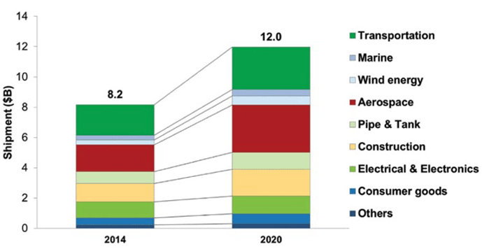
More and more application uses are being found for composite materials and their use is expanding beyond just aerospace applications. As such, you may be wondering how they are manufactured. Composites are manufactured using multiple layers of material, each with different properties, combined into a single structure. By joining them in this manner, the resultant “composite” material is unusually strong and light. It has greater strength, flexure, and more favorable mechanical properties than any of the individual materials used to make the composite. Metal matrix and ceramic matrix composites enjoy widespread use in the wind power, automotive and aerospace industries, among others (Fig. 1), as they offer unique advantages over steel and aluminum. Composite manufacturing is a growing industry and has strong continued prospects for expansion.
The most popular composites, valued for their very high strength to weight ratio, are made of a woven base material such as fiberglass, aramid (Kevlar®) or carbon fiber impregnated with a resin that is hardened into a plastic using heat and/or pressure. The woven material is known as a “prepreg” since it has not yet been impregnated with resin. The resin can be epoxy, polyester, polyurethane, or other plastic in liquid form. The base fiber, such as carbon, has high tensile strength but is not stiff enough on its own to be used as a structural element. The resin can be molded and formed into various shapes but is not strong enough on its own to serve as a structural member. When the base fiber and the plastic are combined, the resultant composite material has both the strength of carbon fiber and the retained shape of the cured epoxy or other hard plastic. This feature, the ability to incorporate the most favorable mechanical properties of each of the constituent materials, is what makes composites such an attractive choice for a wide variety of lightweight structures.
Manufacturing Methods
Hand Layup
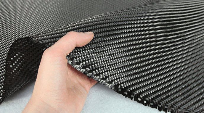
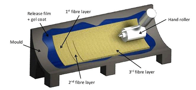
Composite materials are manufactured in different ways, but one of the most common is the vacuum bagging method in which the uncured material is formed in a mold, placed under vacuum, then cured in an oven while vacuum is maintained. This involves starting with a fabric weave of carbon fiber (mat), similar in appearance to a thick woven cloth (Fig. 2), placing it in a mold (also referred to as a tool), and forcing epoxy resin into the weave. Successive sheets of the fabric are then layered onto the first with the epoxy imbedded into and between each layer. This manual process is referred to as hand layup where the successive layers are placed into the mold and the epoxy resin is forced into the mat using a small roller (Fig. 3). Each mat layer can be oriented with the weave rotated 45° or 90° to the one below it to maximize the strength of the final product. The result is a cross-plied layup (as opposed to a unidirectional layup where all the fibers are oriented in the same direction). After the layup is complete, the mold gives the finished part the desired shape, and the part is ready for bagging. The epoxy forms a matrix that allows the part to hold its shape with the carbon fibers residing in the matrix providing the required strength.
Vacuum Bagging
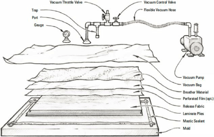
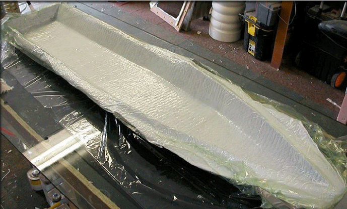
In order to create a useful finished part, the composite material must be held tightly in the mold while the resin is curing. Vacuum bagging is a technique that uses atmospheric pressure to squeeze the resin-impregnated layers (the laminate) together, forcing them to conform to the shape of the mold. After layup is complete, the laminate layers are sealed in an airtight vacuum bag. The bag may consist of a plastic sheet that covers the layers (Fig. 4) or it may utilize top and bottom sheets that enclose the laminate and the mold. In either case, after the bag is sealed and before vacuum is applied, pressure on the inside of the bag is the same as the outside and is equal to atmospheric pressure, which is approximately 1,000 mbar (29.9 in. Hg, or 14.7 psi). A vacuum hose is connected to the bag and a vacuum pump draws the air from it. The air pressure inside the bag is reduced while air pressure outside of the bag remains at atmospheric pressure. As a vacuum is drawn on the inside of the bag, atmospheric pressure on the outside of the bag presses on the bag (Fig. 5) and squeezes the laminated layers of resin-saturated mat together against the mold, serving as a clamp that puts very uniform pressure over the entire surface of the part.
The pressure differential between the inside and outside of the bag governs the pressure exerted on the laminate. The maximum pressure that could be exerted on the laminate by atmospheric pressure if the vacuum pump removed all the air from the bag and achieved a perfect vacuum, would be 1,000 mbar (29.5 in. Hg). As a practical matter, the vacuum system is operated at 400 to 840 mbar (11.8 to 24.8 in. Hg), which generates sufficient pressure, 4,200 – 8,400 kg/m3 (6 to 12 psi) on the laminate to hold the layers together and force it to conform to the mold. This high available pressure permits very complex molds to be used without voids remaining between the layers of laminate or between the laminate and the mold. Atmospheric pressure is not only pushing down on top of the mold but is also pressing on all sides and the bottom of the mold with the same force. Therefore the mold does not need to be rigid enough to withstand the entire force created by the 8,400 kg/m3 (12 psi) pressure on its surface since the sides and bottom are supported by atmospheric pressure. This allows the mold to be relatively lightweight and inexpensive.
Vacuum Pumps for Composite Manufacturing
The central component of the composite cure vacuum system is the vacuum pump. The pump must be capable of drawing the necessary vacuum and it must also be able to provide sufficient displacement. The level of vacuum necessary depends on the shape and complexity of the part being molded. For example, a part with many contours and complex features will require a high vacuum to squeeze the part via atmospheric pressure on the bag. This forces the laminate into the concave mold cavities without creating voids. A flat panel-shaped laminate does not have these cavities and therefore needs a lower vacuum level vacuum to be drawn on the bag.
The flow rate (displacement) of the pump is also important for two reasons. First, the initial drawdown must evacuate all the air beneath the bag within an acceptable time period. This air is a result of voids and cavities between the bag and the laminate prior to the vacuum being drawn, which are a normal result of the manual layup process. The greater the pump displacement, the faster the pump will remove this air resulting in a shorter drawdown period. The second reason pump displacement is important is due to leakage that occurs at full vacuum. After drawdown, the pump no longer needs to evacuate the air under the bag but must be able to displace the air being leaked into the bagged volume through the perimeter mastic or tape as well as through any fittings or pipe connections. It is important to recognize that during the initial drawdown, the pump inlet is at or near atmospheric pressure so the pump is allowed to operate at its maximum flow rate. While under full vacuum after drawdown the pump is operating near maximum vacuum and minimum flow rate. Therefore both the maximum pump flow rate (referred to as the pumping speed) must be considered as well as the flow rate at full vacuum. Pump manufacturers provide pump curves illustrating the flow rate at both conditions. If one of these ratings is ignored during pump selection, the system will either take too long to draw down (while under minimal vacuum) or fail to maintain the required vacuum level after drawdown (at maximum vacuum) due to system leakage.
Vacuum Components for Composite Cure Vacuum Systems
After the laminate materials are laid up in the mold and placed under vacuum, they are cured in an industrial oven (Fig. 6). It is common practice in aerospace and other applications for many parts (50, 100, or more) to be cured at the same time. In these cases, the layup process is often done inside the oven.
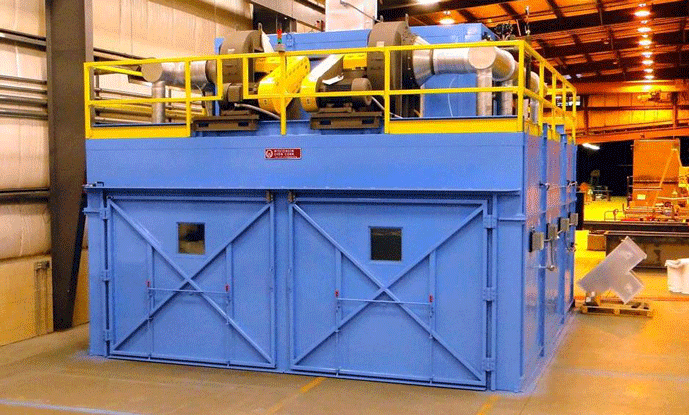
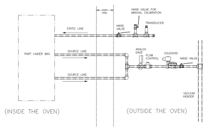
The molds are placed on worktables in the oven while they are at ambient temperature. The workers perform the layup operation inside the oven, connect the vacuum system to the layup (part under bag) via flexible connections, and then the vacuum system is turned on. The vacuum valves, transducer, pump, and other components are located outside the oven, and there are penetrations through the oven wall for the vacuum lines.
One common arrangement is for one or more vacuum source (aka active) connections to provide the vacuum to the part, and for a static (aka passive) line to be connected to the other end of the part (Fig. 7). The source line delivers the vacuum to the part. A transducer on the static line senses the vacuum level. This information is sent to a master control system for recording and control. It is common for a composite cure system to process 50 or more parts having 50 or more sets of active and static vacuum lines. The vacuum pump selection is critical since the flow rate necessary for initial drawdown and leakage can both be considerable. Rotary vane pumps are very common in industrial applications such as these due to their reliability and reasonable cost.
Vacuum systems and the pumps used in the processing of composite materials
In the section above, we introduced composite materials, reviewed the vacuum bagging method for composite manufacture, and discussed the role vacuum systems play. Here we will take a closer look at these systems, and some of the unique requirements of vacuum equipment for composite manufacture.
The Vacuum Pump
The most common vacuum pump used in industrial scale composite curing units is the rotary vane pump. A rotary vane pump is considered a wet, positive displacement pump. Wet, because the air being pumped is exposed to oil used as a lubricant and to help provide the seal. Positive displacement refers to the fact that the pump works by mechanically trapping a volume of gas and moving it through the pump, creating a low pressure on the inlet side.
This type of pump is highly reliable and reasonably energy efficient. It features an eccentrically mounted rotor that contains two vanes which slide in diametrically opposed slots (Fig. 8). The vanes are either spring loaded or rely on centrifugal force to push outward against the stator wall. As the rotor turns, the tips of the vanes trap a volume of incoming air and move it around the circumference of the pump chamber toward the exhaust outlet. This creates a vacuum at the pump inlet due to the void created. During this process, the air is compressed and discharged out of the pump. As the vane continues to rotate, the opposing vane seals the inlet and the process is repeated. A small amount of oil is discharged with the air as a mist. A filter system is employed to remove the oil from the discharged air.

Duplex Pumps
In vacuum curing of composite parts, it is common for dozens of parts to be simultaneously placed in the cure oven, vacuum bagged, then cured under heat. In other cases, one or two very large parts are processed. Either way, the parts being cured are expensive, since many hours of manual layup are required to create each part. Therefore it is important the oven and vacuum system be extremely reliable. A failure in the middle of the process can cost many thousands of dollars if the parts have to be scrapped. In the case of large space rocket components, the value can be several million dollars per load. For this reason, a duplex pump arrangement (Fig. 9) is commonly employed to ensure the reliability of the vacuum system.

The duplex pump arrangement consists of two pumps piped in parallel. Each pump is designed to handle the full flow rate and ultimate vacuum required by the system. During normal operation, both pumps are in use and evenly share the load. In the event of failure of one of the pumps, the remaining pump still has the full capacity required to provide vacuum for the system. Control logic is employed such that upon failure of one of the pumps, its inlet valve is automatically closed, isolating it from the system, allowing the other pump to carry the load. This design has two advantages. First, each pump is normally only required to run at half of the usual system flow rate. This reduces the wear on each pump and extends the service intervals and pump life. Second, this redundancy greatly increases the reliability of the overall system since the likelihood of both pumps failing simultaneously is very low. For example, if each pump has a .005 (.5%) likelihood of failure during a given run, the likelihood of both pumps failing during the same run would be .005 x .005, or .000025 (.025%).
The duplex pump arrangement is not to be confused with a two-stage rotary vane pump, in which two pumps are piped in series and the inlet of one is connected to the outlet of the other. The two-stage pump arrangement is not used to improve system reliability, but rather to enhance the pump performance by increasing the ultimate vacuum achievable.
In a duplex pump arrangement, the inlets to both pumps are piped to a common receiver (aka accumulator). The receiver is then piped to the main header that is in turn connected to the bagged parts. The receiver is a tank that stores a reservoir of vacuum, allowing the pump to cycle less frequently and serves as a buffer between the pump and the bagged parts. A 75 m3/h (44 ft3/min) pump, for example, might incorporate a 0.454 m3 (16 ft3) receiver tank. Receivers are used for both duplex and simplex pump arrangements.
Pump Performance and Draw-Down Time
Both the volumetric capacity of the pump (i.e., the pump “speed”) and the ultimate vacuum of the pump must be considered when selecting a pump for composite curing applications. The speed of the rotary vane pump is not consistent over the entire operating range of vacuum. The pump speed is highest when the pressure at the pump inlet is highest (i.e. the vacuum is the lowest). This often occurs when the system is first evacuating a bagged part and the maximum vacuum has not been reached. The flow capacity decreases dramatically after most of the air is removed from the bagged part and the vacuum on the part increases. When ultimate vacuum is reached, the pump flow rate approaches zero. The pump manufacturer provides curves that show the relationship between the pumping speed and the vacuum level (pressure) at the pump inlet (Fig. 10).

To properly select a pump, it is necessary to determine the time required to draw the air out of the part bags (often referred to as the “draw-down” or “pull-down” time) and achieve the desired vacuum. If this is ignored, the pump may be selected incorrectly such that it will take an unacceptable length of time to draw a vacuum on the bagged parts. As is seen on the pump curve, the relationship between the pump pressure and the pumping speed is highly nonlinear. This is due to the fact that as the pump draws the air out of the bagged parts, the remaining air gets thinner and expands to fill the remaining volume, making the pump less effective at removing the remaining air. There is a relationship (Table 1) between the pump speed at atmospheric pressure (SCFM) and the actual speed at reduced pressure (ACFM). For example, the pumping speed at one half of atmospheric pressure (roughly 15 in. Hg), is ½ the speed at atmospheric pressure (0 in. Hg). This is shown by the fact that the ratio of the volume of SCFM (unloaded pump at standard conditions) to ACFM (pump operating under vacuum) is 2 at 15 in. Hg.

The above factors make it difficult to calculate the pump draw-down time because the pump speed (flow rate) continuously drops as a higher vacuum is achieved during pull down. There is, however, a way to estimate the draw-down time with reasonable accuracy (Fig. 11). This estimation requires a “pull down” factor be applied. Variable A, tank size, represents the desired volume under bag to be evacuated. For example, if an ultimate vacuum of 28 in. Hg is desired, the pull-down factor is 2.75. If the volume under bag is 100 ft3 and the pump speed is 10 ft3/min, the pull-down time is 100 x 2.75 / 10 = 27 minutes. Another way to think of this is that it takes 2.75 times longer for the pump to displace a given volume of air in order to attain 28 in. Hg than it would take the pump to displace that same volume at atmospheric pressure.

Vacuum Control
The most common arrangement for vacuum bagging and curing involves placing many parts in a cure oven and connecting the vacuum system to the parts through penetrations in the oven wall (Fig. 12). The vacuum pump is then turned on and the vacuum is drawn on the part bags. A header pipe connects the vacuum source lines to the pump.
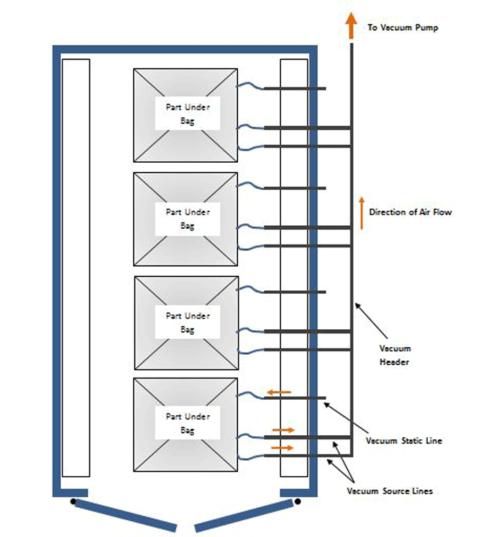
Each of the individual source lines includes a separate solenoid valve, to allow them to be turned on or off individually (Fig. 13). The solenoids are wired to a master control system so they can be actuated remotely. Each static line is connected to the bagged part, usually on the end of the part opposite from the source line(s). The static lines are capped off and don’t allow air to pass to the parts. Their purpose is to monitor the vacuum. A transducer located on each static line verifies vacuum is penetrating the part from the source line and reaching the transducer. Furthermore, the transducer measures the vacuum level and transmits this information to a data acquisition system. The data acquisition system collects and stores this data for each part. Since many of the parts being cured are critical, high-value components for aerospace and automotive applications, it is important this information be stored and traceable to each individual part. The master control system also stores recipes that control the vacuum level, oven cure time and oven temperature for each part.

Individual Vacuum Control
The design described above results in all the bagged parts being at the same vacuum level, since they are all connected to a common manifold. However, it is sometimes desirable to have an arrangement where different parts in the same cure cycle are at different vacuum levels. This requires an alternative design where each source line incorporates a second solenoid valve located between the first solenoid valve and the part. This “bleed” valve allows a slight amount of air into the system at a controlled rate, reducing the vacuum on that part.
When the bleed solenoid valve opens and closes, a closed loop controller monitors the vacuum transducer. If the vacuum is above set point, the bleed valve opens, reducing the vacuum on the part until it reaches set point. If the vacuum on the part is too low, the bleed valve closes, which increases the vacuum level on the part until set point is achieved. Individual vacuum control requires separate vacuum reservoirs be located at each source line.
Vacuum Filters
Since the bagged parts put under vacuum consist of a woven fibrous material impregnated with resin, loose fibers or resin vapor can possibly pass into the vacuum system, causing contamination. It is common to incorporate a filter system to prevent this. The preferred design is to locate a small filter in each source line, to catch contaminants before they reach the vacuum header. An alternative design is to rely on a single main filter located near the pump inlet.
Summary
Composite manufacturing is a growth-orientated technology with aerospace and transportation-related industries leading the way. The increased use of composites, particularly epoxy-based glass, aramid, and carbon fiber materials in recent years has paralleled the growth in commercial aviation and is positioned to meet the demands of “all composite” transportation vehicles in the future. Vacuum treatment of these materials will continue to play a significant role in the success of this technology.
REFERENCES
- Composites Manufacturing magazine (www.compositemanufacturingmagazine.com)
- 3MB Co., LTD (www.3mb.asia)
- University of Liverpool (www.liverpool.ac.uk)
- West System (www.westsystem.com)
- Nextcraft.com (www.nextcraft.com)
- Wisconsin Oven Corporation (www.wisoven.com)
- Edwards Vacuum (www.edwardsvacuum.com)
- Dekker Vacuum Technologies (www.deckkervacuum.com)
- Kurt J. Lesker Company (www.lesker.com)
- Combined Fluid Products (www.cfpco.com)
- Wisconsin Oven Corporation (www.wisoven.com)
