HOT-ZONE CONSTRUCTION
Hot-zone service life is directly related to the type of heat treating process used in a vacuum furnace and to the severe thermal stresses imposed by continuous vacuum-furnace cycles. For example, a by-product of high-temperature sintering is contamination in the form of a vapor, which is deposited on the shielding of the hot zone. Vacuum brazing also creates contamination, which ultimately ends up on the hot-zone shielding. Distortion and contamination are the main factors causing a breakdown of hot-zone components. Distortion is inevitable because thermal cycling is inherent to the process. However, periodic inspection and remediation of hot-zone components together with thorough component cleaning can extend service life.
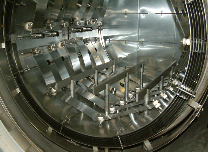
Two main types of hot zone construction used in vacuum furnaces today are an all-metal zone and a carbon-felt zone. An all-metal zone consists of several layers of sheet metal, such as molybdenum, stainless steel, and tantalum, separated by channels. The choice of material depends on operating conditions. For example, a zone that will be subjected to an operating temperature of 2400°F (1315°C) could consist of two inner layers of molybdenum backed by three layers of stainless steel (figure 1). A hot zone intended for use at temperatures to 2600°F (1430°C) generally is made entirely of molybdenum. Reflective heating is used in an all-metal zone; that is, radiation from heating elements is reflected off the inner layer of molybdenum back to the parts being treated. Heat is contained in the hot zone through the use of channels, which create gaps between each sheet metal layer. Each gap creates an area of insulation with each successive layer being cooler.
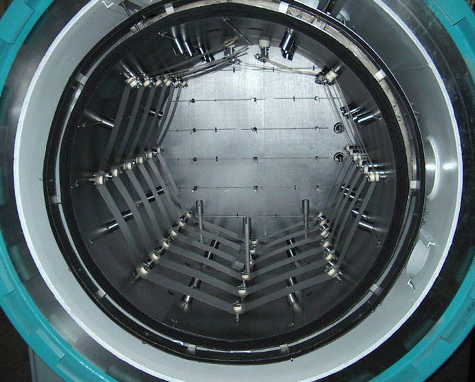
The carbon-felt style hot zone is becoming more popular in the industry due to a somewhat lower cost than the all-metal construction. Although radiation is reflected off the inner layer to a certain extent, this style of hot zone contains heat within the furnace by means of its insulating properties. Carbon-fiber felt is rolled inside the diameter of the zone with an outer layer of molybdenum sheet or a carbon-based foil (figure 2). Spaces are not required between the layers because the porous, permeable felt has excellent insulating properties. Thermal radiation contained inside the zone is reflected back by means of the inner sheet and foil. Graphite boards are sometimes used in place of felt but are losing popularity due to cost and maintenance considerations.
A graphite hot zone tends to absorb moisture in humid climates (unlike an all-metal zone), which is a minor disadvantage. However, this usually is a problem only in applications having critical vacuum requirements.
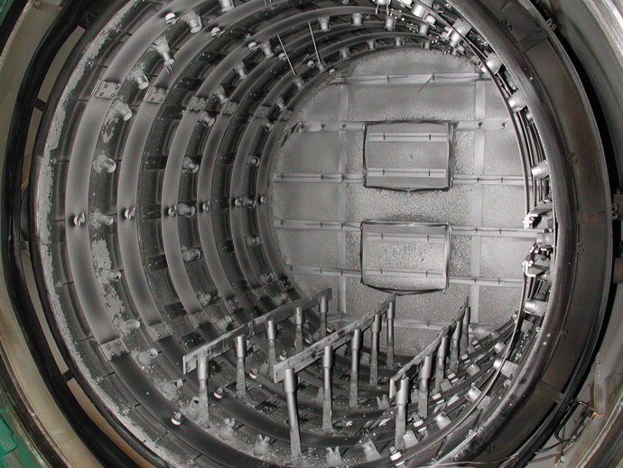
Generally, both hot-zone types use molybdenum for shielding, hold-down rods, and heating elements. Molybdenum requires the most maintenance, which directly relates to hot-zone life. Some degree of distortion occurs in molybdenum components due to thermal shock from each furnace cycle (figure 3). Thermal cycling and contamination are the main factors causing a breakdown of molybdenum. Contamination not only is detrimental to the ultimate vacuum achieved but also results in deposits on all molybdenum material in the hot zone (figure 4). These deposits result in distortion because the material cannot expand and contract uniformly during the heating and cooling cycles. Eventually, the molybdenum tears at the locations of the deposits. Contamination deposits on molybdenum heating elements can cause arcing on the shielding and parts, resulting in further damage.
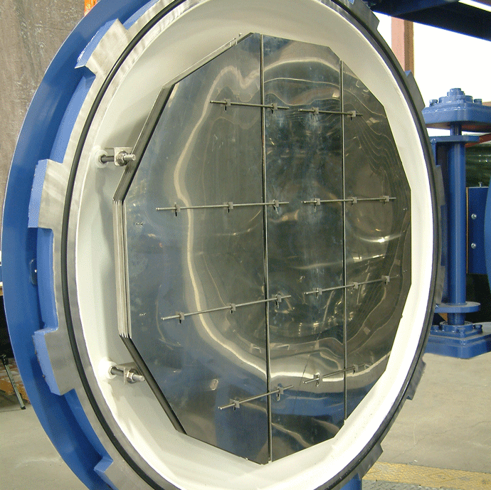
Molybdenum becomes embrittled after a single exposure at a temperature around 2100°F (1150°C) and is easily damaged in this condition from an impact by fixtures and parts. Embrittled molybdenum can be worked (repaired) as long as the material is at an elevated temperature (hot to the touch). A molybdenum component can be returned to a ductile condition for repair simply by heating the area in question using a propane torch. At this point, the material can be bent, cut, drilled, etc. The material returns to an embrittled condition after it cools, which again requires careful handling. Newer doped and lanthanum-alloyed molybdenum are stronger and maintain their ductility even at higher temperatures. The trade-off for the improved properties of these materials is their higher cost.
HOT-ZONE HARDWARE PROBLEMS
A common problem with all hot zones is the shielding between the ring segments and door shield curling back into the hot zone. The material can be returned to its original shape by heating the distorted area as described above and straightening using a pair of pliers. Another problem area involves hold-down rods-the components that keep shielding in place on both the ring and end shield assemblies. Warped rods resulting from stresses due to continual thermal cycling can be straightened after heating similar to the method used for shielding. Rods that can’t be straightened should be replaced so they won’t damage the retaining pins in which they sit. A hot-zone section containing broken retainers must be removed to facilitate retainer replacement.
Heating elements present another area of concern. Elements tend to sag and bend between the element support pins (figure 5), which strains the pins eventually causing them to break. Elements also can be reshaped by heating and straightening, but those that are too distorted should be patched or replaced. Pins that hold the element segments on the support pins should be replaced if cracked or twisted. It is good practice to inspect the ceramic insulators that support the element on the pins while performing this repair. The insulators can become conductive due to a build-up of contamination deposit, which results in a short circuit between the element and ground; the material at the area of the short circuit is vaporized (figure 6). The vapor deposits on the shields or on the parts being processed. A simple test using an electrical meggar can be used to check the ceramic insulators against ground. If the test result is positive, the ceramic can be cleaned using a grit blaster.
The electrical connections between the heating elements and power supply outside the hot zone also are covered by insulators, which should be checked for cracks or pieces broken off. A damaged insulator, in this case, could result in arcing of the connection against the hot zone plenum creating a large hole, requiring removal of the damaged section for repair.
Molybdenum threaded rod and nuts are used to connect the elements and “T” bars. Studs and nuts containing cracks and breaks should be replaced to prevent studs from falling out of the connection hole.
Gas-quenching tubes made of molybdenum and carbon should be thoroughly inspected on a weekly basis. The tubes are subjected to thermal stresses from furnace cycling and from the flow of high-velocity cooling gas, and it is imperative that the tubes are not damaged and that none are missing. Should a missing tube go unnoticed, the quench gas will be directed behind the hot zone shielding, which will distort the layers in an all-metal zone and will result in the breakdown of felt in an insulating zone.
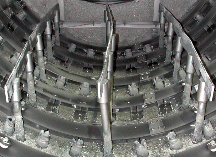
Gaps are included between each section in the hot-zone design to allow for thermal expansion during a furnace cycle. Gaps between each ring segment and between the ring and end shield sections are between 0.25 and 0.375 in. (6 and 10 mm) depending on the size of the zone, but gap width changes over time. When gaps become larger, the heat inside the zone has a direct path to the plenum that supports all shielding. The plenum is made of either stainless or mild steel, which distorts at a different rate than that of molybdenum, creating more distortion inside the hot zone and possibly the furnace chamber walls. Therefore, the gaps in the hot-zone construction should be maintained as close to the design dimension as possible. Generally, this can be accomplished by using the support system that holds the rings and end shields in place.
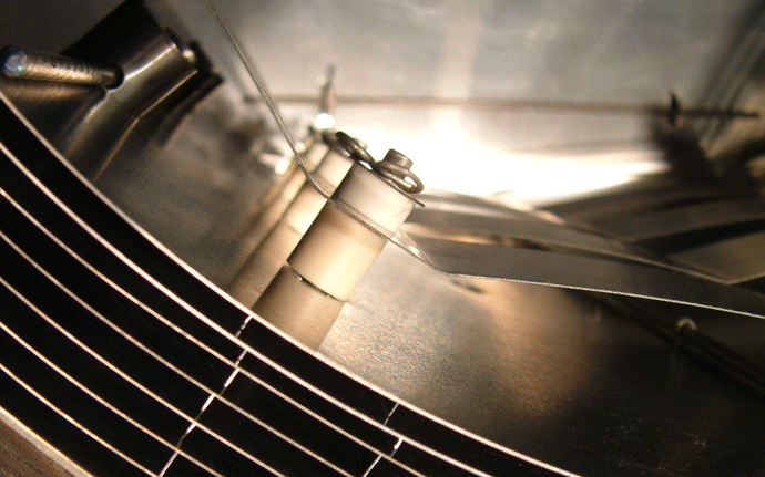
In a graphite felt zone, any noticeable degradation of either the felt or graphite foil must be repaired. This type of repair requires the removal of the degraded felt and installation of a new layer, as long as there is sufficient material to affix the patch on both sides. Usually, this can be done between two hold-down rods. It also is necessary to determine the cause of the felt breakdown and rectify the situation.
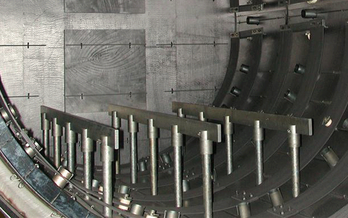
All hot zones require some type of hearth system to support the load being processed (figure 7). If a hearth system fails, the load and fixture holding it could cause catastrophic damage inside the zone. Typically, the hearth is constructed using several pins (generally made of molybdenum) that support rails on which the load sits. The grid or fixture that sits on the hearth is made of a different material (for example, stainless steel, Inconel, etc.) than the hearth itself, which has different thermal properties than molybdenum.
A fixture sagging between the hearth rails imparts tremendous force against the side of the rail when it expands and contracts during a heating and cooling cycle. These forces push or pull the rails out of position making the hearth unstable. Rails can be heated and straightened using a small press.
The pins on which the rails sit also can be damaged during a furnace cycle. The rails sit in slots cut on top of the pins, which are the weakest point on the pin, and can break off. Pins having broken slots are either replaced, or a cap having a slot can be added on the top of the pin. The hearth also should be checked for levelness. Stainless steel washers can be added inside the pin sockets to true up out-of-level hearths.
KEEP IT CLEAN
Clean hot zones are the most productive and maintenance free. In a furnace being cycled continually, contaminants are deposited on hot-zone shielding regardless of the process being run. The best way to ensure that a hot zone is clean is to schedule a “bake-out” run at least once a week. This cycle involves heating the furnace to a temperature of at least 50°F (28°C) hotter than the highest process temperature used. If this temperature is below 2250°F (1230°C), the bake-out temperature should be 100°F (55°C) higher.
Hold the furnace at temperature for at least one hour. A longer soak period can be used depending on the severity of contamination. At the end of the soak period, vacuum cools the furnace to below 300°F (150°C), which takes approximately 8 to 10 hours. (Do not quench the furnace after the soak period.) Heating the furnace above its normal process temperature vaporizes contaminants that have adhered to the hot zone. Quenching the furnace at this point allows the contaminants to redeposit onto the shielding. By comparison, vacuum cooling allows the pumping system to remove the vapors before they have a chance to stick to the hot zone shields.
If the bake-out cycle does not yield the expected results, a run using hydrogen partial pressure can be used. By introducing hydrogen into the furnace during the run, the shields are “scrubbed” by the gas. This run should only stay at the bake-out temperature for 30 minutes because the hydrogen will heat up any part of the furnace that is open to vacuum.
The same principle applies to a furnace process that involves brazing using copper and silver alloys. During the brazing cycle, the alloy being used vaporizes and condenses to the hot-zone shields if the cycle is run under a hard vacuum. By running this process under partial pressure, the alloy will not vaporize due to the lack of vacuum. Operating under partial pressure also allows the pumping system to carry away any contaminants before they have a chance to adhere to the shielding.
