Component parts come in all shapes and sizes. To meet this demand vacuum furnaces have been designed to accommodate many standard workload configurations (Table 1). Despite the almost limitless choices, some common sense rules apply.
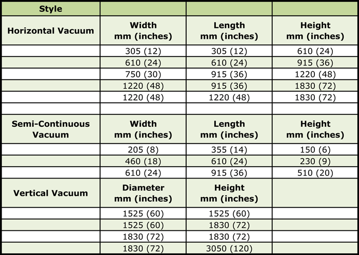
It is important to recognize that loading arrangements generally fall into two classes: weight limited and volume limited. In either case, when loading parts in furnace baskets or onto racks the goal is often to maximize loading efficiency. One must also be concerned with proper part spacing, that is, how parts are situated within the load for optimal heat transfer (e.g. line of sight heating), support and stability of the load at temperature, temperature uniformity, and heat extraction during quenching so as to achieve the desired metallurgical properties and minimize distortion.
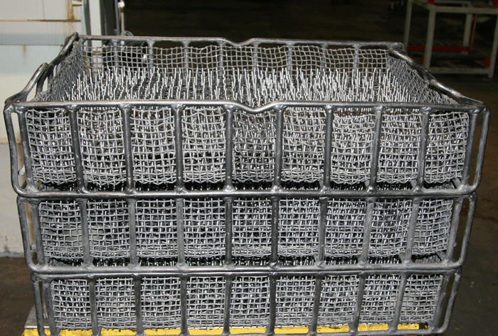
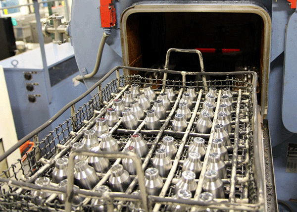
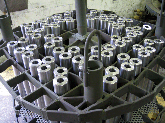
How parts are loaded is very much a function of the geometry of the part as well as the style of the furnace being used. The most common arrangement used in horizontal vacuum furnaces is rectangular baskets designed for stacking or nesting (Fig.1) below. These are typically placed atop carrier grids. Semi-continuous furnaces utilize similar loading arrangements (Fig. 2) below or have parts placed directly onto the carrier grid. Vertical furnaces use fixtures to orient parts in an upright configuration (Fig. 3) below. Cylindrical baskets can also be used.
Loading orientation is very important when trying to minimize distortion in heat treatment. For loading parts in baskets, one can consider individual parts as occupying a cylindrical space that encompasses both the part and a separation space or “gap” between it and adjacent parts (Table 2).

An example of a load configuration for a part having overall dimensions of 38 mm (1 ½”) diameter x 100 mm (4”) overall height is that it will fit inside a typical cylindrical envelope of 38 + 19 = 57 mm (1 ½” + ¾” = 2 ¼”) diameter by 100 + 19 = 119 mm (4” + ¾” = 4 ¾”) high.
Final spacing is dictated by concerns for heating, soaking, flow (of partial pressure or backfill gases), the type and volume of quench media (e.g. oil, gas) and gross load weight. A number of “rules of thumb” used in the industry can help but determining the proper spacing around parts is critical and is often best done by trial and error. In general, the gap around a part should be should be no less than 25% of its envelope diameter and no greater than 75% of the height. Again, one must factor in both process and equipment variables including the type and construction of the quench tank, nature of the process and part mass to name a few.
For example, bearing races of various diameters are capable of being “nested”, one inside the other when creating a workload thus producing an optically dense load. This is done because the furnace space will be volume, not weight limited. However, one must adjust the cycle to allow adequate time for the heat to reach the interior parts. As a result, spacing shown in Table 2 is often doubled. By contrast, when processing other types of thin wall tubing that is not nested, the spacing between parts is often reduced due to the relative ease of heating and cooling.
Calculations Involving Rectangular Baskets
For rectangular baskets a method of determining how many circles of a given diameter can be placed into a rectangle of known size can be expressed as a simple formula:
(1) W/d x L/d = N
where W is the width of the rectangular space available, L is its length, d is the diameter of the part (including separation space) and N is the number of parts that can be loaded into the rectangular space. In this calculation, all fractional parts are rounded down.
For example, a furnace has a workload size of 610 mm (24”) wide x 910 mm (36”) long x 610 mm (24”) high. Shafts with overall dimensions of 38 mm (1 ½”) diameter x 100 mm (4”) long are to be loaded into four (4) rod frame mesh baskets, each 150 mm (6”) high. Parts will be standing vertically inside an egg-crate type separator system. The internal dimensions of each basket (inside the mesh liner) measure 570 mm (22 ½”) x 875 mm (34 ½”) x 140 mm (5 ½”).
For loading purposes we can consider each shaft to be inside a 38 mm + 19 mm = 57 mm (1 ½” + ¾” = 2 ¼”) circular envelope, with an overall height requirement of 100 mm + 20 mm = 120 mm (4” + ¾” = 4 ¾”). Thus we can fit 10 across (22 .5 ÷ 2.25 = 10) and 15 down (34.5 ÷ 2.25 = 15.3 ˜ 15) or 150 shafts/layer x 4 layers/load = 600 shafts/load.
The gross load should be checked against the furnace rating and the “percentage rules” applied to assure that the loading is reasonable. Several different rules apply. First, check that the work area covers no more than 50% – 70% of the surface area of the bottom of the tray and no more than 70% – 80% of the overall height is occupied. Also, if oil quenching is involved be sure that the area covered by the load, basket, and grid is not greater than 50% (agitators) to 75% (pumps) of the total area. In critical quenching applications, these numbers will drop to 25% – 50% (maximum). In the shaft example above, the 150 shafts will occupy 34% of the bottom area 1709 cm2 ÷ 4943 cm2 (265.05 in2 ÷ 776.25 in2) and 79% of the height or 120 mm x 4 layers = 480 mm ÷ 610 mm (4 ¾” x 4 layers = 19 in ÷ 24 in).
In another case, a manufacturer has 6 mm (¼”) diameter x 30 mm (1 ¼”) long fasteners that he will randomly load in mesh baskets for hardening in a batch integral quench furnace. The fasteners have a bulk load density of 2800 kg/m3 (175 lbs./ft3). The furnace has a 750 mm (30”) wide x 1200 mm (48”) long x 750 mm (30”) high workload and 1020 kg (2,250 lb.) gross load capacity. Parts will be loaded into five (5) baskets each having an internal volume of 0.13 m3 (4.5 ft3). In this example, “packing density” is the major consideration in knowing when the center of a load of tightly nested fasteners reaches temperature. This effectively forces us to reduce the furnace capacity because the radiation area through the load is restricted, and hence heat up takes longer. As the “packing density” increases, the rule of thumb “an inch per hour of cross-section” comes into play. A densely packed load of fasteners will NOT be at a temperature in the middle of the baskets if they are overloaded. In this case, the loading should be limited to 25 mm (1”) to 50 mm (2”) deep, depending on the heating efficiency through the load.
If this load were to be carburized, the load should be spread out so that either parts are not touching or the depth of loading is only several layers deep (maximum).
Calculations Involving Circular Baskets
For round or circular baskets a method of determining how many circles of a given diameter can be loaded, or inscribed into a larger circle of known diameter involves calculating the ratio of the diameter of the load circle (D) to the part circle (d) where, if appropriate, the separation distance has been added to d. This ratio, R, can be expressed as
(3) R = D/d
where N, the number of inscribed circles that results, is related to R in Table 3.
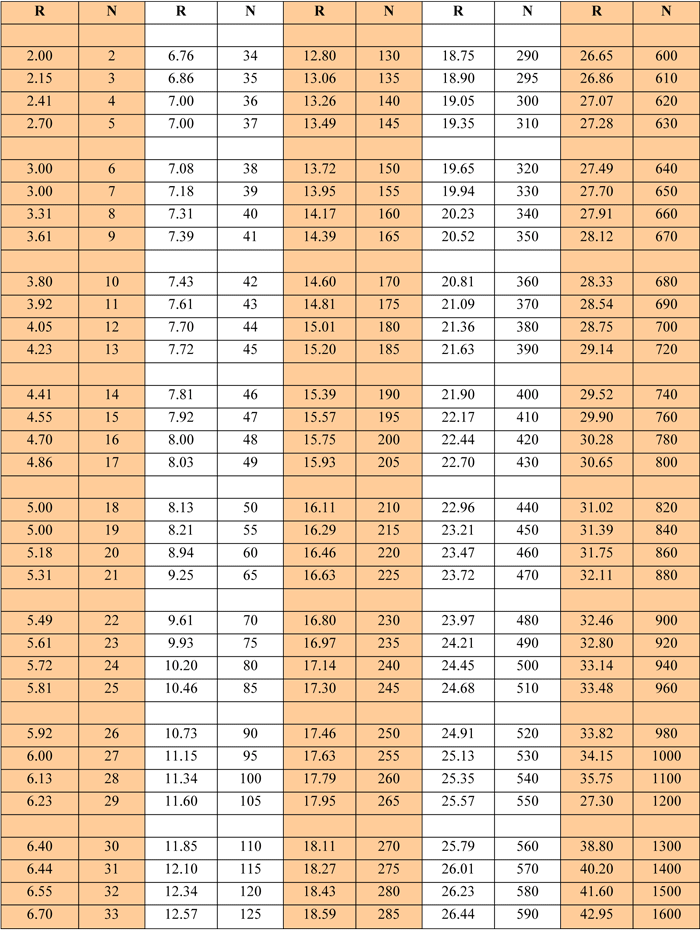
For example, if we want to know how many 13 mm (½”) diameter wires can be placed inside a 125 mm (5”) pipe, using Formula 3 we calculate R = 125 ÷ 13 = 10 (R = 5 ÷ 0.5 = 10), and finding the value nearest to this number in the columns of R in Table 4, we find N = 78, determined by interpolation.
In general, cylinders can be packed in rectangular containers more efficiently than in cylindrical ones because one can vary the length and width of the rectangle as opposed to only the diameter with a cylindrical container.
References
- Herring, D. H., How to Load Parts in Furnace Baskets, Heat Treating Process, November/December 2003.
- Efficient Approach to Packing Cylinders, Design News, October 1975.
- Melisson, Hanes (J.B.N.), Densest Packing of Congruent Circles in an Equilateral Triangle, The American Mathematical Monthly, Volume 100, No. 10, December 1993.
