Vacuum gauges measure the pressure readings in the range from atmospheric pressure down to some lower pressure approaching absolute zero, which is not attainable. Some gauges read the complete range with low resolution and others can only read a portion of the range but with better resolution, usually used for the lower pressures.
There are three groups of vacuum gauges based on the method of operation, mechanical, thermal conductivity, and ionization. For this discussion, we will only talk about the thermal conductivity and ionization gauges because purely mechanical vacuum gauges are generally not used on vacuum furnaces.
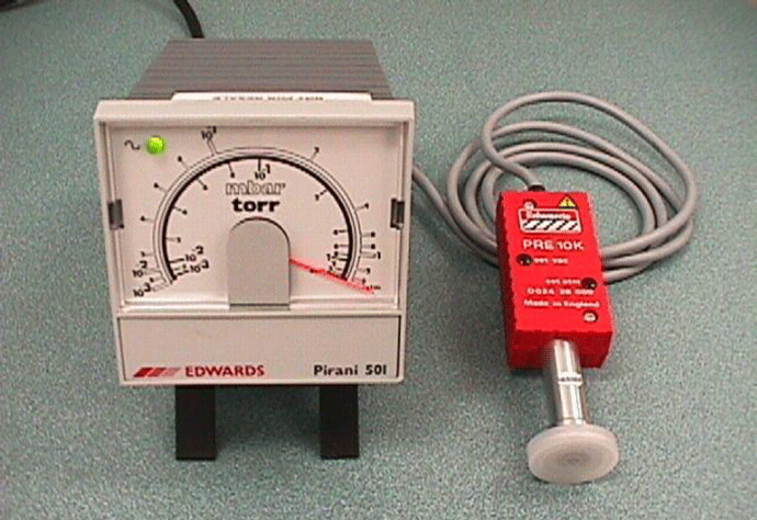
A typical electrical vacuum gauge consists of a sensing head (gauge head) and readout (Fig. 1). It has a power cable to supply power (115V) to the readout and an electrical cable to supply power to the gauge head and also to carry the signal from the gauge head to the readout. Gauge heads are usually mounted vertically, i.e. with the connection downwards. This is to allow the gauge heads to read correctly and also to prevent debris from entering the head.
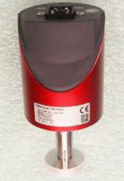
For systems such as vacuum furnaces the high vacuum gauge most used is the Penning cold cathode gauge that indicates pressure from the 10-2 Torr decade down to around 10-9 Torr. It has a robust stainless steel gauge tube and can be dismantled and physically cleaned if it becomes contaminated. (Fig. 2) is actually a Wide Range Active gauge head and incorporates a small Pirani head inside the Penning gauge tube. The Penning type gauge is bulkier than other gauge heads due to the magnets mounted around the gauge tube.
In recent years the measuring range of capacitance manometer gauges (Fig. 3), has been improved that now models can read pressures down to about 10-5 Torr. This allows them to be useful for some high vacuum processes because the heads are also corrosion resistant and are the most accurate vacuum gauge available.
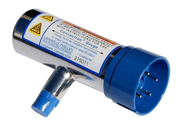
For measuring foreline pressure and chamber roughing pressure there are several options. The thermocouple gauge (TC) (Fig. 4), the Pirani gauge and the Convection gauge. The convection gauge is a hybrid design of the Pirani gauge to enable readings at higher pressures. They all read from about 20 Torr down to about 1 x 10⁻³ Torr (1 micron) and have a good resolution from 1 Torr to 1 x 10⁻³ Torr.
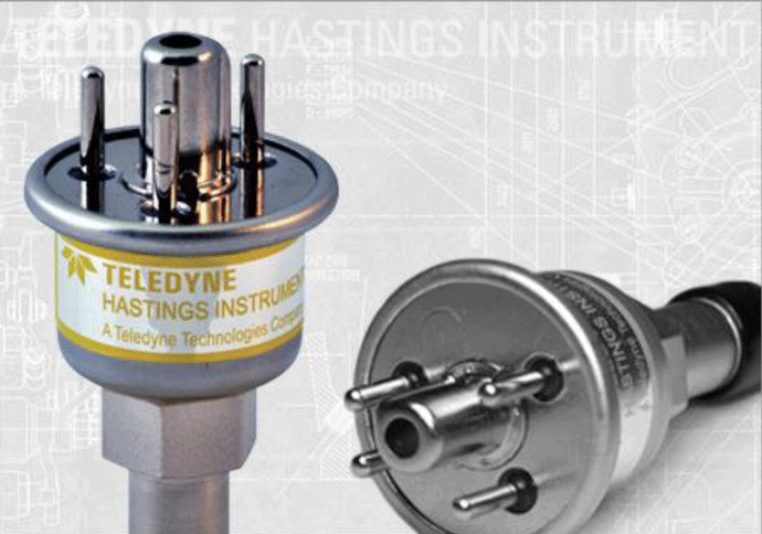
Often, US-made TC and Convection gauge heads are supplied with a 1/4″ NPT threaded connection as standard. Threaded connections are difficult to seal for use in vacuum systems as there are often small leaks through the root and crest of the threadform. (How many of these gauge heads have you seen with the black sealing compound stuck around the connection?) The modern “NW” rubber O-ring connection is a much better option, much less prone to leak and easier to put on and take off.
Early Vacuum Gauge Designs
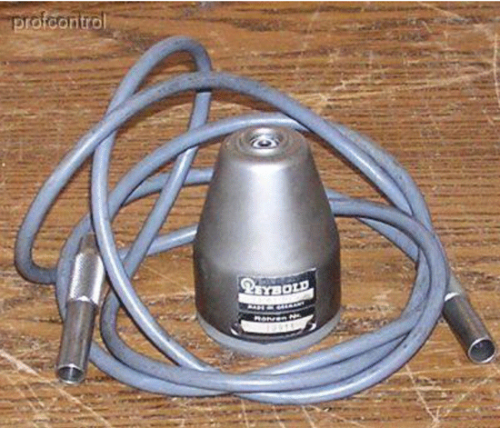
Early designs of vacuum gauges used a coaxial cable to connect the gauge head to the readout because the signal from the gauge head was small, in milliamps or millivolts. Co-axial cables have a layer of crisscross thin copper wires wound around the central wire or wires to reduce signal loss. These cables often used different designs of plugs and sockets to ensure that a specific gauge head couldn’t be plugged into another type of gauge readout (Fig. 5). The electrical circuits in the readout were only compatible with that specific gauge head signal.
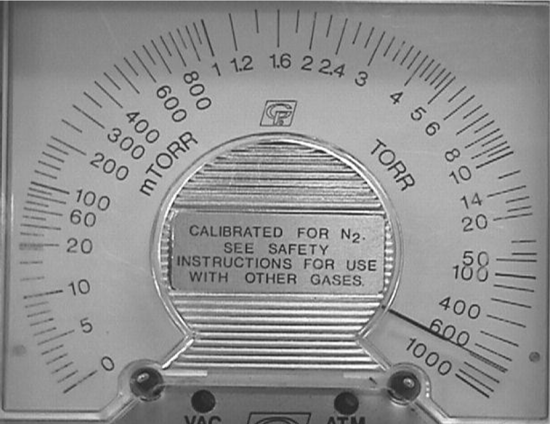
Readouts were of the analog design using a needle moving along a scale to show the pressure being indicated (Fig. 6). Once the small-signal reached the readout it would be amplified by the electrical circuitry inside the readout box in order to make the needle move. For a system such as a vacuum furnace, the gauge readouts would be mounted in an instrument cabinet with other controls where they could be monitored easily. Outputs from the back of the gauge readout would also allow the pressure signals to be sent to a chart recorder so that there was a record of the vacuum readings and other process parameters. Prior to the use of computers for data storage, chart recorder plots were the best way of keeping the details of a process cycle. In many industries, aerospace, for example, each critical metal component must have a record of every process it goes through in the event of a failure during use.
Modern Vacuum Gauge Designs
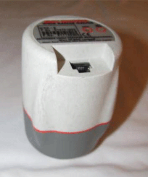
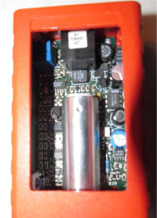
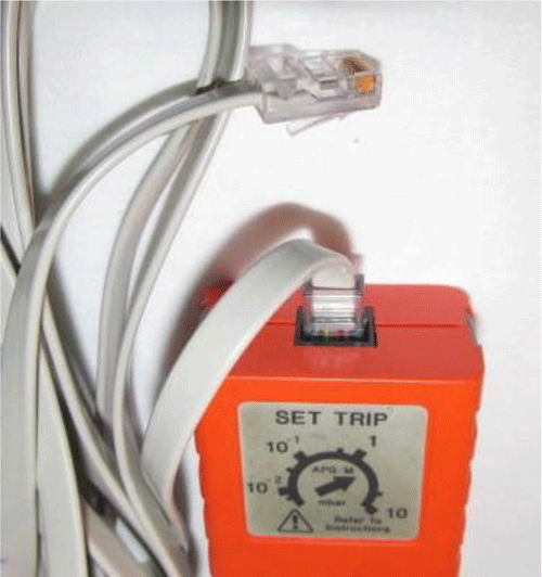
In the eighties, when solid-state electronics became the norm, there was an important technological change in the design of vacuum gauges. The relatively large circuit boards used to amplify the gauge head signal started to be made much smaller using surface mount technology. This miniaturization allows the much smaller circuitry to be mounted right in the gauge head envelope rather than in the readout box (Fig. 7). Then, as the gauge indicates the pressure the signal is amplified at the gauge head into a larger 0 to 10-volt signal. This makes the gauge head a self-contained transducer. The larger signal does not need to use the somewhat expensive co-axial cable as the loss of signal is negligible. Modern “active” gauges, as they are known, use inexpensive telephone wire and typically RJ-45 plugs (Fig.8).
The bonus of this amplified signal to the OEM (original equipment manufacturer) is that it can be taken directly into a computer control system and the gauge manufacturer’s readout box is not needed. This is a nice cost-saving, perhaps to help pay for the computer control system. The computer can be programmed to relate any voltage in the 0 to 10-volt signal to the equivalent pressure and then display it on the screen. This is similar to a “lookup table” where different voltages are tabulated to show the equivalent pressure reading for each voltage. For vacuum gauge users with simple or small vacuum systems, a readout box is still available and it may indicate the pressure ranges from one or more types of gauge head, depending on the manufacturer and model.
At the same time as the electronics changed, digital readout displays (Fig. 9) were introduced. A digital display shows the pressure reading, the decade of pressure being indicated (power of 10), and the vacuum unit being used.
One drawback of using the telephone-style cables for several different types of gauge heads, instead of the specific co-axial cable for each type of gauge head, is that now the readout or computer system doesn’t know what type of gauge head is attached to it. The voltage signal from each type of gauge head will relate to different pressures based on the pressure range being read and the shape of the voltage/pressure curve for that head. The readout or computer system needs to know which lookup table has to be selected to match the gauge head signal. To overcome this problem, in the vacuum gauges that I am most familiar with anyway, the voltage from 0 to 2 volts is used to identify the specific gauge type attached to either the computer control system or the readout. Each type of gauge head has a specific voltage signal that allows the controls to identify it. When the vacuum gauge is switched on a signal is sent from the control box (or computer control system) to the gauge head to determine its specific indicator. Once the gauge head is identified the control selects the correct lookup table for the gauge head and switches it on. Other manufacturers may identify the gauge heads in a different manner.
More recent improvements in electronic vacuum gauges have linearized the “s” shaped voltage/ pressure curves to simplify the lookup tables. This gives makes the voltage signal directly proportional to the pressure. Some vacuum gauge heads have a digital readout mounted right on the head itself. This may be useful for small lab sized vacuum systems but less useful for larger systems with central control panels.
Vacuum Furnace System Gauges
If you have a typical vacuum furnace it is normal to have at least three electronic vacuum gauge heads mounted on the system to monitor the level of vacuum at selected positions. These gauge heads send signals back to the control system and the pressure readings are used to ensure that the vacuum pumps are working correctly and that the process chamber is at the correct low pressure (vacuum) for the specific process. These vacuum gauges can also be set to read whichever vacuum measuring unit you want to read, generally torr in North America and mostly mbar or Pascal in Europe. Although the vacuum unit “microns” (1/000th of 1 mm Hg) was used on older medium vacuum gauges, and is still popular in refrigeration dehydration applications, it has mostly been replaced by “Torr” or “mTorr” on industrial and scientific vacuum gauges. (1 mTorr = 0.001 Torr = 1 micron = 0.001 mm Hg).
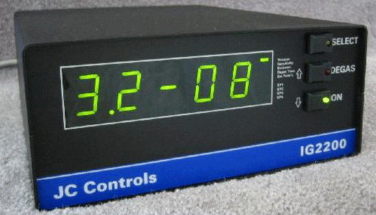
Three vacuum gauge heads are used due to the different pressures in the system. The vacuum gauges usually have set points (Fig. 8) associated with them that are used to open and close valves to automatically operate the system. These can also be used to shut the system down in the event of sudden pressure rise and perhaps prevent damage to the system.
It is important to understand that the pressure reading from a gauge head is the pressure inside the gauge head itself and may be slightly different from where you would actually like to read the pressure, i.e. in the center of the work zone. Gauge heads are situated as close to the place where you want to know the pressure as is practical.
Foreline Gauge Head
The first step of a vacuum furnace pumping cycle is generally to evacuate the oil diffusion pump to a low enough pressure that the heaters can be switched on. To monitor that pressure a TC, Pirani (Fig. 1) or Convection gauge head is mounted in the vacuum piping near the exhaust connection of the diffusion pump. In North America, this pipeline is called the fore line (of the mechanical pump) but can also be referred to as the discharge line (of the diffusion pump). The gauges mentioned typically have a measuring range from around 20 Torr down to 1 x 10⁻³ Torr depending on the manufacturer and the model.
Later in the furnace process cycle, when the diffusion pump is at working temperature, the vacuum chamber has been “roughed out” and the crossover is made from roughing to high vacuum pumping, this gauge head is used to monitor the diffusion pump discharge pressure. Oil diffusion pumps work with hot oil vapor jets and the discharge pressure must be kept below the critical discharge pressure (CDP) of the specific pump and fluid used for the vapor jets to work correctly. A setpoint (Fig. 8) on this gauge head allows the control system to close the high vacuum valve if the discharge line pressure approaches the CDP.
Chamber Roughing/Crossover Gauge Head
The second vacuum gauge head is another TC, Pirani or Convection (Fig. 10) type and is mounted on the vacuum chamber to measure the pressure attained during the “roughing” phase of the evacuation. This is often the second step of the evacuation when the mechanical pumps are connected directly to the chamber through the roughing line.
Once the diffusion pump has heated up and is pumping against the closed high vacuum valve, the foreline valve is closed and the roughing valve opened to allow the mechanical vacuum pump to rough out (evacuate) the vacuum chamber to the crossover pressure. In small systems, this may take only one or two minutes and with clean oil and minimal outgassing, the pressure in the discharge line will stay below the CDP. As system volumes get larger in size, especially in the work chamber, the roughing cycle may take many minutes. To ensure that the CDP is not exceeded while the main mechanical pump is on the roughing cycle, a small mechanical holding pump (5 to 10 cfm capacity) is added to the system at the discharge side of the diffusion pump to keep the discharge pressure at a safe level. Many vacuum furnace users will be familiar with the holding pump.
High Vacuum Gauge Head
The third gauge head, mounted on the chamber, is generally an ionization gauge or capacitance manometer to measure the high vacuum level needed for the specific process. The position of vacuum gauge heads on vacuum furnaces can be important depending on what is mounted inside the chamber. For the process, it is necessary to know the pressure where the process takes place, usually in the middle of the chamber. The gauge head, however, is mounted on the outside of the chamber and can only measure the vacuum inside its own envelope. Therefore there has to be a factor used to estimate when the process area vacuum level is reached. This would be a trial and error process during the testing of a furnace and also the manufacturer’s experience with previous systems.
The vacuum gauge head can only indicate the pressure inside its own envelope because that is where it either reads temperature change in a hot filament (TC gauge), measures current change due to the change of resistance in a filament (Pirani gauge) or indicates a millivolt signal due to the number of gas molecules being ionized (Penning gauge). For that reason, the gauge head needs to be mounted as close to where the measurement is needed. This is not always easy, especially with chamber mounted gauge heads. Caution must also be taken not to let the specific process have “line of sight” into the gauge head. This is more important in processes such as vacuum deposition, for example, where the gauge interior could be contaminated by the material being evaporated or sputtered. This type of problem can be prevented by installing a small shield inside the chamber near the gauge head entry point. Penning type gauge heads (also called cold cathode gauges and inverted magnetron gauges) are not switched on until the pressure is reduced to around 10-2 Torr and then switched off again as the pressure rise to that point. At pressures above 10-2 Torr, there are more oxygen molecules present and the gauge head interior can become oxidized. Heavy oxidation or flakes of oxidation can short out the gauge head.
Mechanical Vacuum Pump Gauge Head
There is one more position in the vacuum system where a gauge head can be useful. That is one mounted near the mechanical vacuum pump inlet, on the pump side of an isolation valve. At any time the vacuum system doesn’t pump down to the expected pressure or at the correct time, the first item to check is the mechanical pump. That would also include the Roots booster pump (sometimes called a blower) if one is mounted above the mechanical pump. Mounting a gauge head, or having a valved connection that a gauge head can be connected to, close to the pump inlet is useful for checking the mechanical pumps for correct operation. Leaving this gauge head in position at all times open to the vacuum line may allow it to be contaminated by oil vapor from the mechanical pump. For that reason, a connection is often installed with a shut-off valve and a gauge head installed if the pump needs to be checked. A version of the TC gauge is available with battery operated readout for portability. Such a gauge may be useful in this case.
This article deliberately does not explain how each gauge head works as there are a number of other documents that do that very well. The choice of gauge types and placement of gauge heads was thought to be more relevant for the readers of this newsletter.
References: Technical training material developed by the author.
Some pictures used to illustrate this article were copied from the internet, and not specifically approved by the respective manufacturers. Other pictures are of products owned by the author.
Copyright Howard Tring, Tring Enterprises LLC Vacuum & Low-Pressure Consulting.
