By now, most maintenance departments should have a plan in place for schedules repairs and maintenance during the summer months, especially if the plant has a shutdown for vacation. The part of the vacuum furnace system that I know best is the vacuum system, so I will concentrate on this.
The summer maintenance schedule should cover all the vacuum pumps on a vacuum furnace. For some it will just be mechanical pumps, the rotary piston pumps and the Roots booster (or blower); for others, it will include the oil diffusion pump or pumps and the small rotary vane holding pump if used.
In addition, consideration should also be given to the vacuum pipelines, the vacuum valves, the vacuum gauge heads and cables and any other sensors that are part of the system. These are the components that connect the pumps together, connect the pumps to the vacuum chamber and make the whole system work correctly. Lastly, don’t forget the controls cabinet. There may be gauges that should be calibrated or gauges that may need an upgrade. Whatever work is done, plan ahead to have the parts kits or replacement pumps ready to go and keep a precise record of what work is done in the vacuum system log book.
It is very difficult to remember what exactly was done if you rely on someone’s memory. If it is written (or entered) into the system logbook or database there is a record of the work and any changes made. It is documented so that operators on all shifts can see it, and if there is a problem later, that information can be reviewed for a possible cause. Once the summer maintenance is finished the whole system should be tested to determine the base pressure, and that should be recorded.
Let’s take a quick look at the components of the system that may be selected for work during a shutdown and review the work that could be carried out. Always follow all the safety rules in place.
 |
|
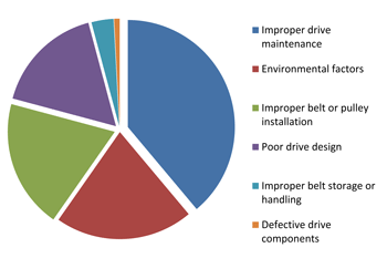
Fig. 1 Vee Belt Drive Problems.
|
Oil sealed, rotary piston pump
This pump can be tested for the lowest pressure by closing the inlet valve and checking the vacuum level produced up to that valve. Check the vacuum against previous tests and record it. If the vacuum level is good and the pump is not any noisier than normal, there may not be a lot of work needed.
The vee belts should be checked for wear and for the correct tension. The vee belt suppliers can supply a small tension tester that is not much larger than a thick writing pen. While the vee belt drive cover is off, also check that the flywheel and pulleys are aligned, fastened tightly and that there is no keyway wear (Fig. 1). Look for any shaft seal leakage. If the bearings have not been replaced for some time, a check of the bearings may be a good idea. This requires the removal of the vee belt pulley from the pump shaft. Once the pulley is off a dial indicator can be mounted on the pump so the indicator tip touches the top of the pump shaft. Then a lever can be used, blocked up at one end to be horizontal under the shaft and lifted at the other end, to see if there is any movement in the bearing. If there is movement and it exceeds about 0.005 inches the bearings should be replaced. Always replace both bearings.
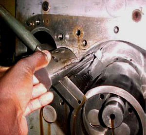
An area that tends to see wear is in the hinge bar area at the pump inlet (Fig. 2). Any dust entering the vacuum pump at the inlet can become entrained in the oil and then causes wear on the lower hinge bar especially. To remove the hinge bars one side plate has to be removed.
An oil change would normally be a standard part of the pump check, and the valves should be checked for wear and for broken springs. Larger rotary piston pumps will also have a water cooling circuit; the connections should be checked for leaks or damage.
Most of these pumps will have an exhaust filter and the element should be inspected and changed if needed. If the exhaust line has a drip leg, it should be drained.
Roots vacuum booster
 |
|
Fig. 2 Hinge Bar Removal.
|
Roots vacuum pumps are often sent out for repair if it is needed because there is some special skill required to ensure that the pump rotors are timed correctly. This was an area that we spent extra time on when training maintenance technicians at the Edwards/Stokes factory. Some booster pumps use helical gears with shaft shims used to correctly position one gear to the other. Others used straight gears and a male and female tapered ring assembly (Ringfeder) to lock the gears in place. When a booster pump accelerates the drive shaft twists due to the torque and may actually hit the driven rotor if the tolerance between the rotors is not correct. Similarly, on shut off, the driven rotor may contact the drive rotor. If this happens the noise will be heard!
In these pumps there are shaft seals to check, bearing and seal lubrication oil to be changed, gears to be checked for wear and rotors to be checked for damage. Be very careful when checking rotors. Injuries can occur if your hand is in the pump and the rotors turn.
Most Roots boosters are either direct drive or vee belt drive. For direct drive boosters, check the coupling spider and replace if necessary; for the vee belt drive check the vee belts as noted above.
One manufacturer has a direct drive Roots booster with a hydraulic clutch as the coupling. This is more difficult to service than an ordinary coupling and is probably best left to a service technician that works on them regularly.
Oil sealed rotary vane pump
Although the rotary piston pump has been the most used vacuum pump for vacuum furnaces in North America, some systems use large rotary vane pumps as the primary or fore pump. They typically run faster (1800 rpm) because they are direct drive pumps rather than the 500 rpm or so of the rotary piston pumps. In my experience, they are best suited to clean systems and medium-duty operation at most. Small rotary vane pumps are used by many manufacturers for holding pump duty on the diffusion pump, during the roughing cycle.
These pumps should have the oil changed, checked for shaft seal leaks, be tested for base vacuum and be cleaned externally, including the motor vents. The small holding pumps I have seen in plants have often been covered with an oil film and are dirty. They will stay cooler if they are clean and any oil leakage may be seen a bit easier.
These pumps should have a minor service about every two years if in regular use, and the blades may need to be changed every other time.
Rotary vane pumps should also have a mist filter installed and the elements should be changed at least once a year.
 |
|
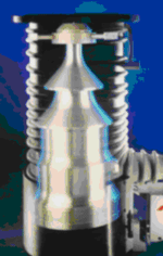
Fig. 3 Diffusion Pump Jet Assembly.
|
Oil diffusion pump
These vacuum pumps have no moving parts but do require some checks. As they are large and heavy in many cases it is a lot of work to drop them off the system inlet flange or baffle valve flange. Support the pump while the inlet flange bolts are removed, but be careful not to damage the heaters under the base of the pump.
Oil diffusion pumps have an oil drain at the base of the boiler. Never open this drain while the pump is hot and working under vacuum. When the pump is not running the oil quality can be checked using the drain connection. If this connection has an O-Ring seal, always replace it with a new seal if the drain has been opened. This O-Ring is in a hot zone and will always deteriorate due to the heat. When the drain is opened that O-Ring will be hard and brittle, reusing it will result in a leak.
The vapor jet assembly (Fig. 3) inside the pump body should be checked for oxidized fluid buildup (black tarry goo) on the edge of the jets. There may also be oxidized fluid in the boiler. This should be cleaned out as it affects the efficiency of the pump and can give an unstable base vacuum.
Most industrial oil diffusion pumps use silicone oil as the operating fluid, replacing the hydrocarbon oils used many years ago. Silicone oils are much less prone to oxidation than the hydrocarbon oils, but will still oxidize if they see too much oxygen from the inlet gas stream. This will mostly occur at crossover from roughing to fine pumping if the crossover pressure is too high or the high vacuum valve is opened too quickly.
Change all O-Ring seals, check the heaters and clean off the cooling coils. Check the cooling lines for lime build up. If heaters need to be replaced ensure that the boiler surface is clean and flat, and the heater surface is clean, so that they have good contact. Any grit present may cause a hot spot which can lead to early heater failure. When the diffusion pump is started up again, ensure that the cooling water flow is correct.
 |
|
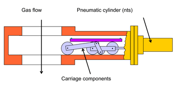
Fig. 4 Gate valve carriage.
|
Vacuum valves, traps and baffles
These smaller components of the system should all be checked for correct operation and the O-Rings changed. Often the valve plate O-Ring may be damaged by dirt in the system and have lost some of its elasticity, especially the high vacuum valve, so it should be changed. If the pneumatic cylinder on the high vacuum valve has a speed controller on its control solenoid valve, it should be checked for correct operation when the valve opens. If your vacuum system uses gate valves the carriage linkage (Fig. 4) should be checked for wear and the valve plate O-Ring replaced. The interior of the gate valve is open to system contamination such as abrasive dust and the carriage bearings can become worn. Traps and baffles should be checked and cleaned or serviced as necessary.
Vacuum pipelines
These lines should be checked for contamination on the inside surfaces. Above the diffusion pump, there may be traces of silicone oil and this should be cleaned off so it does not reach the hot areas of the vacuum chamber.
The roughing line and foreline should also be checked for back-migrating mechanical pump oil and cleaned as necessary.
Vacuum gauge head, control cables, and readouts
In older vacuum systems there may be individual gauge readouts for every gauge head on the system. These readouts would be mounted in the control cabinet. It is a requirement at many plants that these gauges are calibrated on a regular basis, either to a master gauge at the plant or to a master gauge at NIST or another qualified testing laboratory.
In newer control systems the gauge head signals are taken directly into the computer controlled system and displayed on the screen. However, the gauge heads still need calibration, especially for ISO2000 qualified plants and those processing critical parts such as aircraft components.
On many older vacuum gauge heads, and some new ones, the standard mounting connection is a 1/8” NPT thread. Threaded connections are difficult to make vacuum tight and can allow tine air leaks into the system. Although there is some metal to metal contact when a thread is connected there are spaces in the thread form that allow the very tiny air molecules to leak into the system. Many threads are sealed using PTFE plumbers tape but this will not seal the thread completely. Consider the use of silicon sealant which can be wiped into the thread grooves and will seal the thread much better. Best of all; consider upgrading the gauge heads to models that use NW O-Ring seals. This will almost certainly eliminate leakage and changing heads in the future will be easier. Check all gauge head cables for damage.
Conclusions
Making all these checks and servicing as needed results in a vacuum system that performs well and helps to ensure good quality parts being processed. Document all work done so that others can refer to the notes later on.
Copyright Howard Tring, Tring Enterprises LLC Vacuum & Low-Pressure Consulting.
