 |
|
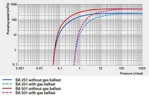
Fig. 1 Rotary piston pump speed curve (Photograph courtesy of Pfeiffer-Balzers)
|
In many vacuum systems, especially those where the chamber is large has a large internal surface area and the chamber load adds extra surface area, the pump down can be slowed substantially when the chamber pressure drops to the range where the water vapor molecules on the surface desorb and have to be pumped away.
Pressure and temperature determine when this vapor desorbs, but at ambient temperature, around seventy-two degrees Fahrenheit or twenty degrees Centigrade the vapor desorbs from about 50 Torr down to about 0.1 Torr. The vapor pressure of water at ambient temperature is about 18 Torr, so that is where maximum desorption may occur.
Oil sealed rotary vane pumps and rotary piston pumps have a fairly constant pump speed from atmospheric pressure down to a pressure of about 10 Torr (Fig. 1). At lower pressures, the effective pumping speed reduces until the ultimate vacuum of the vacuum pump is reached. At the ultimate vacuum, i.e. the lowest pressure a specific pump can reach, the effective pumping speed is zero.
If the vacuum system only uses a mechanical vane or piston pump, when the vapor starts to desorb the rate of pressure drop will slow as the mechanical pump works at pumping away the large volume of vapor. In some cases, the chamber pressure may rise if the amount of vapor exceeds the ability of the pump to remove it from the system. A long pump downtime will increase the processing time and the overall cost of running the process.
 |
|
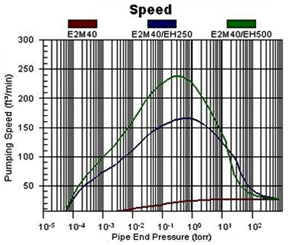
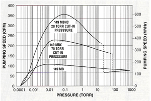
Fig. 2 Root pump speed curves
|
To handle this large vapor load a vacuum pump is required that has a bell-shaped pumping speed curve and has a high pumping speed in the pressure range where the water vapor is generated. The vacuum pump that meets this need is the Roots vacuum booster pump. From the Roots pumping speed vs. pressure curve (Fig.2), you see that the highest pumping speeds are from about 10 down to about 0.01 Torr. On average a Roots pump will increase the system pumping speed by about 10 times.
The Roots vacuum booster design
The Roots pump is generally called a booster when used for vacuum applications and a blower when used for low positive pressure applications. Dresser-Roots still use the original Roots name for their products but, as the patents expired years ago, many versions of the Roots mechanism are made by other manufacturers of vacuum boosters and low-pressure blowers.
 |
|
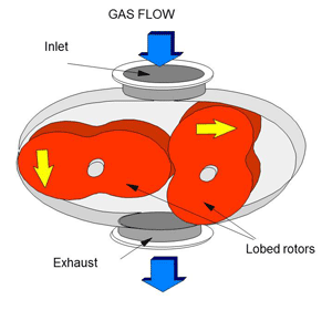
Fig. 3 Roots lobed rotors
|
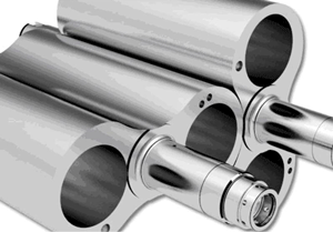
The basic Roots design consists of two figure-eight shaped lobes rotating at high speed inside a stator. (Fig. 3) One rotor is driven by an electric motor and a pair of timing gears drives the second rotor so that neither rotor touches the other. When building or rebuilding these pumps the rotors have to be synchronized or “set” so that no contact occurs on startup and shut down when the shafts are subject to the highest torque loads. To reduce the torque developed the rotors are usually hollow and balanced (Fig. 4). There are clearances between each rotor and also between the rotors and the stator including the ends of the rotors. The interior of this vacuum pump is not lubricated so it is called a “dry pump”. The bearings at each end of the rotors and the timing gears are lubricated, but that lubrication is prevented from reaching the pumping cavity by sealing methods such as lip style shaft seals and labyrinth seals.
As this single-stage mechanism is a dry pump with unsealed clearances in the pumping cavity the mechanism is not very efficient. It may have a compression ratio of only about 20:1, compared to an oil-sealed rotary piston pump compression ratio in the region of 100,000:1.
As the Roots pump lobes rotate they trap gas molecules entering the inlet of the pump in the lobe cavity and this gas is swept around the pump interior trapped between the lobe and the inside of the stator. There is no pumping through the center of the pump because the offset lobes are almost touching at that point. The swept gas is then delivered to the exhaust area of the Roots pump where the backing pump will pump it away and in turn exhaust the gas to atmosphere.
 |
|
Fig. 4 Hollow Roots rotors
|
Part of the reason that the Roots mechanism is inefficient is that there are no valves in the mechanism; the other reason is the clearances between the lobes and the stator mentioned previously. There is also a tri-lobe design of the Roots mechanism, and this is slightly more efficient as the back leakage of gas is reduced. Both dual lobe and tri-lobe mechanisms pump large volumes of gas mainly due to the high rotational speed.
If a Roots style vacuum booster pump was to be used as a single pump on a vacuum system (very unlikely), the compression ratio limits the best vacuum it can produce to about 38 Torr. (atm. press 760/20 = 38 Torr) This is not a low enough pressure for most vacuum applications. Due to the low compression ratio of the Roots pump, it is always used with a backing pump in vacuum applications. The backing pump may be any oil sealed or dry pump of a suitable pumping capacity for the application.
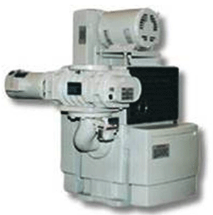
In vacuum furnace applications the pump combination of choice in the USA has generally been a Roots booster backed by an oil-sealed rotary piston pump. (Fig. 5) If there are vapors from the process that may affect the vacuum pump oil a multi-stage dry pump may be used as the backing pump.
The Roots style vacuum booster combined with a suitable backing pump will improve the pump down in two ways:
- The high pumping speed of the vacuum booster pumps away the dry gases and desorbing water vapor very quickly, up to ten times faster, and
- The lowest pressure (ultimate vacuum) of the pump combination will be one decade better (ten times lower) than the backing pump can produce on its own.
 |
|
Fig. 5 Roots and Piston Pump set
|
Operating pressure range for Vacuum Booster Pumps
If the Roots style vacuum booster was started at atmospheric pressure it would require a large HP motor to drive it. At atmospheric pressure, the backing pump has the design and horsepower to work efficiently.
The electric motor for the vacuum booster is sized to suit the power needed after the initial evacuation by the backing pump to about 100 Torr or below and when water vapor starts to desorb from the surfaces. The actual starting pressure varies between different system volumes, applications, and manufacturers.
Starting the vacuum booster at a lower pressure allows a smaller motor to be used, but precautions must then be taken to prevent the vacuum booster operating above the maximum rated pressure ratio. If the pressure ratio is exceeded the motor will be overloaded and may fail.
To prevent motor overload manufacturers have used three methods of preventing motor overload:
- Using a pressure switch connected to the motor controls set to a safe starting pressure
- Designing a pressure operated by-pass valve into the vacuum pump body that “unloads” the pump if overload conditions occur, and
- Incorporating a fluid clutch between the motor and the pump designed to slip if an overload condition occurs.
 |
|
Fig. 6 Pressure switch settings
|
a) With the pressure switch controlling the startup, the setting can be varied to suit the chamber volume and application. (Fig. 6) Manufacturers give little guidance on starting pressure apart from advising that running the booster with a differential pressure that is too high will overheat the pump.
If the pressure differential does reach a higher than the recommended level, i.e. the backing pump is not able to pump away the booster exhaust fast enough; heat will be generated by this compression. Because the pump rotors do not touch the stator walls they cannot give up the heat generated and as they become hotter they expand. It is possible for the rotors to expand enough due to this heat that the clearances are reduced to the point where metal to metal (rotor to stator) contact occurs. This will badly damage the pump. Overheating may also cause damage to parts such as the oil seals and the bearing lubricant.
On pump set startup the backing pump starts to evacuate the chamber until the pressure switch allows the vacuum booster to start. Then the pumping speed will take a big jump in a couple of seconds to the point on the vacuum booster speed curve at that pressure, perhaps around 80 to 20 Torr.
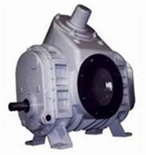
b) If the vacuum booster is of the pressure relief valve design, this valve is built into the stator of the pump. (Fig. 7) It is a spring loaded valve that will open if the pressure differential across the vacuum booster exceeds the selected level. Varying the spring strength allows adjustment of the opening pressure. When the bypass valve opens, gas at high pressure on the exhaust side of the vacuum booster is allowed to recirculate to the inlet side of the pump. This “unloads” the pump and reduces the power being used to a safe level.
This can be compared to an air compressor working on a heavy-duty cycle. When the selected pressure is reached the compressor valves are held open by an unloader mechanism so that the compressor doesn’t use too much power. When the pressure drops in the system the unloader fingers retract allowing the valves to open and close normally and the compressor resumes its work.
In this design, the booster pump may be started with the backing pump at atmospheric pressure, but the bypass valve will not allow the pump to work much until the pressure ratio across the pump allows the bypass valve to stay closed. Another option is to incorporate a time delay in the startup of the vacuum booster, allowing the backing pump to reduce the chamber pressure to a certain level before the vacuum booster is started.
 |
|
Fig. 7 Bypass design Vacuum Booster
|
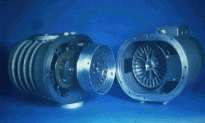
c) One manufacturer offers an alternative design to prevent motor overload when pumping from high pressures by incorporating a fluid coupling. (Fig. 8) The vacuum booster pump is started at the same time as the backing pump if pumping a large mass of gas creates a high-pressure ratio across the booster pump the fluid coupling will slip. The result is that the electric motor continues to run at 3600 rpm but the vacuum booster pump idles because of the fluid clutch “slips”. As the backing pump reduces the system pressure the pressure ratio across the vacuum booster pump reduces to the point that the fluid clutch starts to engage and accelerates the Roots mechanism to full speed. This can be seen in the speed curve for the vacuum booster and backing pump. (Fig. 2)
The manufacturer shows this as a benefit on their design because the vacuum booster starts to pump at close to atmospheric pressure and as it increases to full speed a faster evacuation time results.
The basic vacuum booster that uses a pressure switch to start it (a), and the vacuum booster that incorporates a spring-loaded bypass valve (b) are both available in vee belt drive and direct drive versions. Suppliers offer systems where the vacuum booster runs somewhere between 1800 and 3600 rpm. The vee belt drive option allows the drive speed to be designed to suit the specific pump downtime specified. The direct-drive models generally run at 3600 rpm. Designers must remember that the efficiency of the Roots design vacuum booster is best at the higher speed, typically that of a 3600 rpm motor. The fluid coupling design vacuum boosters (c) use a 3600 rpm motor (in the US) and have no speed options.
Vacuum pump sets using Roots vacuum boosters
 |
|
Fig. 8 Fluid coupling halves
|
In general, most vacuum systems that use the vacuum booster with a backing pump evacuate the vacuum chamber directly through the vacuum booster pump. The vacuum booster mechanism rotates (freewheels) with the gas flow at high pressures and then starts to pump at the design point. The system could also have a bypass pipeline around the vacuum booster to maximize the initial pump down from atmospheric pressure to the startup point of the vacuum boosters. At that pressure, the bypass valves would close to allow direct pumping through the vacuum booster pump.
Due to the additional costs involved with additional piping, at least three additional pipeline valves, and the controls, most systems do not include this design. The few seconds gained in the evacuation time compared to the additional cost are seen as inconsequential.
Smaller capacity vacuum boosters have a top inlet and bottom exhaust, and some can be directly mounted on the backing pump using a suitable spool piece. Larger capacity vacuum boosters have a side inlet and side exhaust and have their own mounting base whether vee belt drive or direct drive.
In systems with very large volumes to evacuate (space simulation chambers) or applications where a large volume of outgassing occurs (steel degassing) the pump set or sets may have several Roots vacuum boosters in series with a high vacuum pump backing them. The backing pump may be an oil sealed vacuum pump or a more modern design multi-stage dry vacuum pump.
Vacuum booster pumps are extremely useful pumps to reduce the evacuation time whenever large volumes of gas and/or water vapor have to be pumped away. The mechanism is quite simple and the pumps are very reliable when proper checks and maintenance are used.
Copyright Howard Tring, Tring Enterprises LLC Vacuum & Low-Pressure Consulting.
