 |
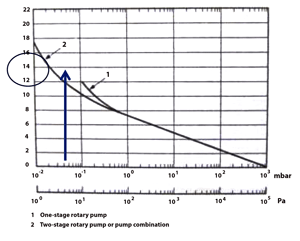
| Fig. 1 Pump down factor curve chart. Published in most editions of Edwards Vacuum product catalogs. |
Resistance to gas flow through components that make up a vacuum system has a considerable effect on the pumping speed and pressure obtainable within the system. Any pipe or component that gas has to flow through is a hindrance to the flow of that gas, i.e. it offers resistance to the flow. It occurs in the roughing line, the foreline and the high vacuum piping and affects the amount of time taken to evacuate a vacuum chamber to its required base or process pressure.
For example, if a large vacuum chamber is connected to its vacuum pump using a long small bore pipe the gas flow down the pipe will be difficult and the gas will be removed from the chamber very slowly. There is a high resistance to gas flow and the conductance of that small bore pipe is low.
Let’s first look at a simple vacuum system, using a single mechanical vacuum pump, the vacuum chamber if often mounted right above the inlet to the vacuum pump.
In this case calculating the time needed to evacuate the chamber is a simple matter, using the equation
T = FV / S
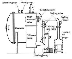 |
| Fig. 2 Typical vacuum furnace vacuum pumps. Photo courtesy of “Modern Vacuum Practice” p. 223, written by Nigel Harris and reprinted with permission from the author. |
In North America the units used in this equation for simple vacuum systems are usually T = time in minutes, V = volume of chamber in cubic feet, and S = pumping speed of the vacuum pump in cubic feet per minute (cfm). The units used must be consistent. F is a factor taken from the curve shown in Fig. 1 and is a correction used to allow for the reduction in pump speed as the pressure drops.
Often, the designer needs to select the correct size of vacuum pump to suit a certain pump down time. For selecting a pump size the equation becomes S = FV / T
In Fig. 1, at a pressure of about 6 x 10⁻¹ mbar, the curve splits into one curve for a one-stage pump and another curve for a two-stage pump. If the process is one where an oil diffusion pump is used to evacuate the chamber into the high vacuum range, the mechanical vacuum pump is generally a two-stage pump. A single-stage rotary piston pump with a Roots blower (or vacuum booster) is considered the equivalent of a two-stage pump. This is due to the fact that the Roots blower reduces the pressure by about one decade from the one-stage pump ultimate vacuum as well as adding a much higher pumping speed to the system once it is at full pumping speed.
Assuming the chamber has a volume (V) of 120 cu ft, (about 5 feet diameter and 6 feet long) the vacuum pump connection is no more than 1 ft. long where conductance is not taken into consideration, and the vacuum required is 6 x 10⁻² torr (60 microns). From the chart (Fig. 1) the factor F is close to 11. This chart shows mbar on the pressure scale and the conversion is 8 x 10⁻² mbar (a 3/4 ratio). The designer wants to reach the pressure in 10 minutes. (This chart is from Europe and mbar is used as the pressure unit)
So the formula becomes S = 11 x 120 / 10 which becomes 1320 / 10 = 132 cfm
To allow for outgassing in the system and other unknowns a vacuum pump with 150 cfm pumping speed would appear to be a good selection.
Putting the selected pump size into the pump down time version of the equation gives us:
T = FV / S and T = 11 x 120 / 150 which becomes 1302 / 150 and T = 8.8 minutes
 |
|
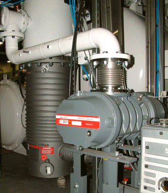
Fig. 3 Vacuum furnace roughing line length. Photograph supplied by VAC AERO. |
This gives a small safety factor to allow for process outgassing, but some processes may need a larger pump if the outgassing from the furnace and product surfaces is large, i.e. when using cellular insulation or if the plant is in a very humid area.
Now let’s compare that result for the same chamber volume with a more normal pipeline arrangement for that large volume.
In vacuum systems the term conductance is used rather than resistance. Conductance is the direct value of how much gas will flow, per meter of pipe, at a specific pressure (or average pressure) in that pipe.
Conductance is the reciprocal of Resistance C = 1 / R
An informal definition of conductance is the capacity of a pipe to allow a volume of gas (at any pressure) flow from one end to the other in unit time. Units are generally liters per second (l/s or l.sec-1) but can be shown in any unit of volume per unit of time.
(In this discussion I will use the format l/s for units as sometimes using the scientific notation x-n can be confusing when pressures are shown in the same format)
The definition is the equation C (conductance) = Q (throughput) / P1 – P2 where P1 is greater than P2
This equation can be manipulated (by substituting Q / S for P) to give Seff = Sp x C / Sp + C
(Throughput Q = P x S)
 |
|
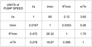
Fig. 4 Pump Speed conversion table. Recreated from the original in “Vacuum System Design”. |
With these equations we can now compare the “actual” pump speed and the “effective” pump speed to see how piping length and diameter affects the roughing stage pump down time.
In a typical vacuum furnace the chamber would also have an oil diffusion pump mounted on it and other pipelines and valves are used to allow the furnace to be evacuated by the pumps in the correct sequence. A popular design would be similar to that shown in Fig. 2, where the oil diffusion pump is connected to the high vacuum valve. The piping from the main pump set also connects to the exhaust of the diffusion pump and a holding pump is included in the backing line of the diffusion pump to be used during the roughing stage of the cycle.
A real-life piping layout is shown in Fig. 3 which is a typical pump set for a vacuum furnace. For this discussion we will concentrate on the length of the roughing line. This roughing line, from the mechanical pump inlet up to the connection at the high vacuum valve appears to be at least 6 feet. Just to confuse the reader, most available curves and charts are from Europe and show mbar and meters so this is about 2 meters. For the sake of the discussion the piping size is 6” (close to 152mm).
The last conversion needed is to convert the selected pump speed of 150 cfm to l/s units. From Fig.4 we see cfm x 0.472 = l/s, so 150 cfm = 70.8 l/s.
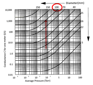
To determine the “effective” pumping speed of the selected vacuum pump, at the closest point of the roughing line to the chamber, the last parameter needed is the conductance of the roughing line at pressure required of 6 x 10⁻² torr. This can be taken from Fig. 5 that shows conductance “per meter” of various diameter pipes at different pressures.
Note on the chart, or off the top of the chart, that at pressures approaching atmospheric pressure conductance is high and little or no restriction on pump speed is seen. As the pressure drops the conductance value drops by a factor of about ten for each decade of pressure drop. For the chosen 100 mm pipe the conductance curve flattens out between 1 x 10⁻¹ and 2 x 10⁻³ torr and is constant at about 100 l/s below that pressure.
At 6 x 10⁻² torr, conductance C = 1000 l/s (per meter)
 |
|
Fig. 5 Conductance in 1 m long pipes. Photo courtesy of “Modern Vacuum Practice” p. 320. as above. |
As the pipe is 2 meters long the actual conductance C = 500 l/sec
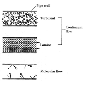
In the area where the curve is about 45° the gas is in viscous or continuum flow. Where the curve flattens to a horizontal line the gas is in transitional flow, and once the curve is horizontal gas flow is in molecular flow. A pictorial analogy of different flow regimes is shown on Fig. 6. Transitional flow will be a changing mix of laminar and molecular flows.
Now let us see what the effective pumping speed will be at the chamber end of the roughing line at the required pressure of 6 x 10⁻² torr.
Seff = Sp x C / Sp + C Seff = 70.8 x 500 / 70.8 + 500 Seff = 35400 / 570.8
The effective pump speed at the chamber end of the roughing line Seff = 62 l/s
Converting 62 l/s back to cfm we see 62 x 2.12 = 131 cfm
In this example, with an effective pumping speed of 131 cfm, there is no excess pump speed to take care of outgassing as the pressure drops. The pump size (Sp) may have to be increased to about 200 cfm.
If the roughing line was 3 meters long, for the same pump the effective speed would be 124 cfm at that pressure. That represents about a 17% loss of pumping speed, which would extend the pump down time past the 10 minute specification.
 |
|
Fig. 6 Gas flow diagrams. Photo courtesy of “Modern Vacuum Practice” p. 320. as above. |
If you check back to Fig. 5 and look at the conductance for a 70 mm bore pipe (about 3” bore) at the required pressure of 6 x 10⁻² torr, you will see the conductance has dropped to about 300 l/s per meter of pipe or only 150 l/s for the 2 meter pipe we used in this example. That would indicate that the 100 mm (4”) pipe is a much better pipeline size for this example than a 70 mm (3”) pipe.
Conductance does change as the pressure changes, so a designer may calculate the effective speed for each decade of pressure. For mechanical piston and vane pumps this would really only be necessary from where the specific pipe size starts on the conductance chart. This is because the pump speed is fairly constant at higher pressures.
Calculating effective pump speed is more important when a Roots blower is used because its pump speed is in the shape of a bell curve. To estimate pump down time the average pump speed for each decade of pressure would be used as Sp to calculate the pump down time for each decade of pressure and then add up the times to find the total time.
There are other factors that should be taken into account when calculating pump down times; the two main considerations are the gas being pumped and the gas temperature. The number of bends in the piping, surface finish inside the pipe and conductance through the valves will all affect the calculations.
If the pipeline has two different diameters of pipe, the conductance for each length is calculated and used to determine the overall conductance of the pipeline.
This comparison of conductance in vacuum lines shows that it is an important consideration when designing a process chamber and selecting the mechanical vacuum pumps.
(When preparing a technical article containing equations and numbers there is always the chance that an error has been made converting from one unit to another and back again even with the numbers having been double checked. I trust that at least one reader will check the numbers and let me know if there is an error.)
 |
| Fig. 1. Throughput in a Vacuum Furnace. |
Above, we discussed gas molecules, gas flow and mentioned the term conductance. Now we will talk a bit more about conductance in vacuum system piping and why it has to be taken into consideration in the design of a typical vacuum furnace or similar vacuum system. Firstly though, we will discuss Throughput.
Throughput
Have you ever wondered why vacuum pipes and connections are of several different sizes on any vacuum system? I would suggest that most users don’t really give it any thought. It is what it is. So let’s look at the sections of a vacuum system and again try to visualize those gas molecules, which are so tiny we can’t see them, and understand the conditions at different places in the system.
Pumping speed of large mechanical vacuum pumps is usually indicated in cubic feet per minute. That can be denoted in several ways; cfm, cu ft /min or ft3 min-1. This is also shown in metric terms as cubic meters/hour, liters/min and l/min also shown as m3 hr-1 and l min-1.
Although the last terms are the most modern, in training I tend to use “cfm” and “l/min” as easy terms to write, and not to use negative powers of ten. In this case the “-1” denotes that time is the divisor, under the line, in the written equation or formula, i.e. per unit time, but some students who are new to vacuum technology or engineering terms think of negative powers of ten as a vacuum or a reading of pressure lower than atmospheric pressure.
So pumping speed units indicate the volume of gas being pumped in a certain time, but they do not relate that pumping speed to any pressure term. If the pressure term is added then we can determine the mass of gas that is flowing at that point in the system.
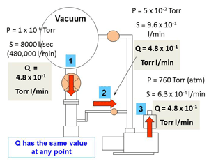
Throughput is a constant at any point in the vacuum system, during normal operation. (Fig. 1) In this example I have assigned a pumping speed “S” for the diffusion pump of 8000 l/sec. That makes the diffusion pump inlet diameter about 20 inches (about 500 mm). The vacuum chamber pressure “P” is shown as 1 x 10⁻⁶ Torr which is a typical pressure for many vacuum applications. (Remember that 1 x 10⁻⁶ represents a 1 millionth part of 1 Torr)
The gas, in the vacuum chamber at 1 x 10⁻⁶ Torr, (position 1) is in molecular flow, where the gas molecules move in a random direction and collide more frequently with surfaces inside the chamber than they do with other molecules. The pumping speed is entirely dependent on the inlet size of the diffusion pump; the larger the pump inlet, the more gas molecules will enter the pump.
As the gas molecules pass through the vapor jets of the diffusion pump they are compressed to a smaller volume and higher pressure, as shown in the backing line (position 2). At a pressure of about 5 x 10⁻² Torr the gas molecules are now in transition from molecular flow to viscous or continuum flow. (This backing line may have a 3 to 6 inch diameter depending on the combination of diffusion and mechanical pumps used.)
The gas molecules in transitional flow now move down the pipeline to the lower pressure generated at the inlet of the mechanical backing pump where they are compressed again, up to atmospheric pressure, and exhausted from the system (position 3).
From this example we learn a bit more about gas molecules moving through the vacuum furnace system. At a low pressure in the vacuum chamber a huge volume of gas is first compressed in the diffusion pump by a factor of about 10,000 times, from 1 x 10⁻⁶ up to 1 x 10⁻² Torr. That gas is then compressed about another 15,000 times in the mechanical pump allowing it to be exhausted into the air at 760 Torr. Neither vacuum pump can compress the gas from the vacuum chamber pressure up to atmospheric pressure on its own, but working as two pumps in series it can be done successfully.
The example shown starts at an already low pressure in the vacuum chamber. If we look at another set of numbers with the vacuum chamber pressure at around 1 x 10⁻³ Torr, throughput Q would be 1000 times larger at 4.8 x 10² which is 480 Torr l/min. Because P will remain in the same range at position 2 and the same at position 3, calculations show the pumping speed S also about 1000 times higher at those places in the pumping system.
 |
| Fig. 2. Conductance in pipes. |
Conductance
The conductance between two points in a vacuum system is expressed as the quantity flow rate of gas flowing through a device divided by the resulting pressure drop.
C per meter = Q / P1– P2 and is expressed in liters per second (l/sec)
Conductance values are used to determine the “effective” pump speed at the vacuum chamber, which can be quite different from the “rated” pump speed of the vacuum pump at its inlet connection. This knowledge is used to select the correct size of mechanical vacuum pump to rough out the vacuum chamber in the required time.
The roughing line shown in Fig. 1 runs horizontally from the side of the vacuum chamber and then an elbow turns it downwards to run to the mechanical vacuum pump inlet. There is always a roughing valve in this pipeline to allow the roughing line to be opened and closed as needed. The valve has its own conductance rating and some manufacturers will show that in their valve literature. For this simple example we will ignore the valve conductance and only consider the pipeline which may have a total length of 2 meters or 3 meters depending on the system design. We will look at both options to see the difference.
If the mechanical roughing and backing pump is similar to a Stokes 212, having a rated pumping speed (Sp) of 150 cfm, it will have an inlet size of 3 inches. That is close to the 70 mm pipe size shown on Fig. 2 so we will use the values of conductance for the 70 mm pipe size on that graph. To complete the calculation we have to express the pump speed (Sp) in l/sec. We multiply 150 cfm by the factor shown in Fig.3 which is 0.472 to give a pump speed of 70.8 l/sec.
The conductance varies with pressure so we need to compare different pressures to try to visualize the “big picture” – of gas molecules that we can’t see. The pressure used is the “average pressure” in the pipeline being studied.
 |
| Fig. 3. Pump speed conversions. |
The first pressure to consider is 1 Torr as it is close to the highest pressure on the Fig. 2 chart. (At pressures above 1 Torr the higher values of conductance allow lots of gas flow and the pump speed loss is much lower.)
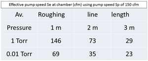
If we do the same calculations for the roughing line at an average pressure of 1 x 10⁻² Torr, a 100 times lower pressure, let’s see the results.
 |
| Fig. 4. The effect of roughing line conductance. |
These numbers are tabulated in Fig. 4 to make them easier to read.
In another article we can look at how conductance may affect pumping speed above the oil diffusion pump and in the backing line.
Conclusions
For throughput: the pressures at different points in the system show the very high compression ratios developed by the oil diffusion pump and mechanical pump. Compare them to the compression ratio of a typical car engine which is about 8 to 1.
For conductance: as the roughing line pressure drops below about 1 Torr the effective rough pumping speed at the chamber is reduced considerably as the roughing line becomes longer, due to conductance losses in the piping.
Roughing pipelines should be as short as possible, and as large a bore as practical.
Note: If the roughing line has an oversized bore to increase the conductance, it also adds extra volume to the system that has to be evacuated. At some point the time needed to evacuate the added volume cancels out the increased effective pump speed at the chamber and no improvement is seen.
References:
Part of this article was abridged from the student notes of an Edwards Vacuum training course titled “Vacuum System Design” from 2001. The equations used are from “Modern Vacuum Practice”, written and published in the UK by Nigel Harris.
Copyright Howard Tring, Tring Enterprises LLC Vacuum & Low-Pressure Consulting.
