 |
|
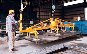
Fig. 1 Lifting with the aid of Suction Cups.
|
In this article, we’re going to take a step away from vacuum pumps and systems and write about general applications that use vacuum in the process.There may be some applications you have heard about and some, hopefully, that may be new to you. Whenever a vacuum (a pressure lower than the surrounding atmospheric pressure) is used in a process it will generally fall into one of the Five Main Reasons for using Vacuum. In some cases, a process may use vacuum for two of the five reasons. This month I will discuss the first of these reasons, in no specific order.
1. To Provide a Working Force
First, a short explanation of the two vacuum measuring units used in this article.
We know that standard atmospheric pressure is 14.7 lbs. in-2 and that your real life atmospheric pressure varies up and down a few percentage points from the standard depending on a) weather conditions in your area and, b) your altitude above sea level.
Remember that “low” pressure is the same as “high” vacuum, and conversely “low” vacuum is the same as “high” pressure – but still below atmospheric pressure in the vacuum industry. I have written a small number and read many technical articles about vacuum and it is very difficult to ensure that these terms are consistent throughout.
In the example below we also have to understand that the vacuum measuring units read in opposite directions and we have to change one of them. Does that sound confusing? Yes, it is.
 |
|
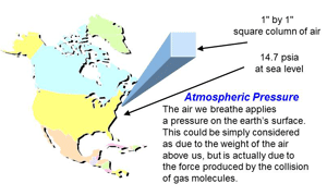
Fig. 2 Atmospheric pressure
|
Atmospheric pressure is the pressure developed by molecules of air colliding with each other, in a one-inch square column of air reaching from sea level up into the sky. Another way of looking at it is the weight of the air molecules, 14.7 lbs., in that same one-inch square column, giving 14.7 lbsf. in2. (Fig. 2) At atmospheric pressure, the reading on the vacuum gauge would around 14.7 psia (pounds per square inch absolute is another way to indicate lbsf. in2 and sometimes easier to write) and as the vacuum level improves or rises, the pressure drops towards 0 psia. No vacuum system has ever been able to create exactly 0 psia – a perfect vacuum – but some scientific vacuum systems have created pressures lower than the pressure on the moon’s surface.
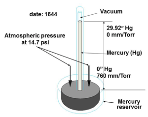
The inches of mercury range, used by Torricelli in his mercury barometer (Fig. 3) has 30 inches of mercury column being supported by atmospheric pressure pushing on the surface of the mercury in the main container. This scale starts at 0” Hg at atmospheric pressure and rises to around 30” Hg at what is often called full vacuum or hard vacuum in some industries such as the refrigeration industry. Although standard atmospheric pressure is equivalent to 14.7 psia and 29.92 “Hg vacuum gauges will show scales of 15 to 0 and 0 to 30 respectively. These are not accurate scales and the numbers are rounded out. To allow us to compare the two scales we will turn the inches of mercury readings around.
Let’s get back to the actual example of using vacuum to do work.
If your vacuum system is under any level of vacuum there is a pressure differential between the inside and the outside of the volume being evacuated. This pressure differential can be used to do work. (Fig. 1)
 |
|
Fig. 3 Torricelli’s mercury barometer.
|
In this application, the lifting frame has six suction cups and it appears that a sheet of thick steel is being lifted and moved. Let’s “do the numbers” and see how much weight the suction cups may be able to lift. In the “rough vacuum” range vacuum readings are often stated using the 0 to 30 inches of mercury scale. For this type of application a rough vacuum pump is used, i.e. a vacuum pump that can produce a vacuum between about 5” Hg and about 29 “ Hg.
It is a wide range, the equivalent of from 635 Torr to 25 Torr on the vacuum gauges generally used in the vacuum heat treating industry, and there are a number of vacuum pumps that can produce a vacuum in that range. However, if the vacuum pump selected has to develop a vacuum of at least 26” Hg and also have a pumping speed requirement of 10 cfm, the selected vacuum pump may be an industrial style reciprocating piston pump similar to an air compressor. This type of vacuum pump is of the same design as a reciprocating air compressor but the valves are reversed. The pumping speed would be selected based on the number of suctions cups used, the number of lifting frames used at any one time and to allow for leakage if, for example, there is debris under the lip of the suction cup.
If the effective size, the inside diameter where it touches the lifting surface, of the suction cup is 6 inches, we can calculate the effective surface area that is available for lifting the product. For this example we can round out the numbers being used as a safety factor will be applied as we make our calculations.
A circle has an area of pi r2. For the six inch diameter suction cup this becomes 3.142 x 3 x 3 = 28.278 square inches. Let’s use 28 square inches, times 6, which gives a total lifting area of 168 square inches.
 |
|
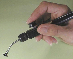
Fig. 4 A vacuum “pick” for lifting small items.
|
Now we need to calculate the pressure differential between atmospheric pressure and the vacuum level inside the suction cup. To calculate this we need to convert the inches of mercury vacuum level stated above to psia and there is an easy ratio between them. One is 15 to 0 and the other is 0 to 30. This is a 2:1 ratio.
If the vacuum pump can evacuate its storage tank (receiver) to about 26” Hg, we have to assume some loss in the piping and vacuum hoses that connect the receiver to the suction cups. Let’s say that loss is 2” Hg. So our effective suction cup vacuum is 24” Hg. Now we need to turn the reading around and convert it to psia.
30 – 24 = 6 and then 6 divided by 2 = 3 psia.
Atmospheric pressure is 15 psia so the differential pressure that can be used for lifting, in this example, is 15 – 3 = 12 psia.
Now we go back to the total lifting area supplied by the six suction cups and multiply it by the differential pressure. That gives the following:
168 x 12 = 2016 lbs. of lifting force, just over 1 ton.
Lastly, we need to apply a safety factor to that number, as we don’t want that steel plate falling on the operator’s toes even if his shoes have steel toe caps! Perhaps a 60% safety factor would be used for this type of product, giving the suction cup frame a maximum lifting capacity of about 1200 lbs. The safety factors applied will vary depending on the weight, size, shape and surface finish of the part being lifted.
This example shows where vacuum, or more correctly a pressure differential created by using a vacuum, can lift a heavyweight. Vacuum lifters are used in the automotive industry to move windshields into position, in the printing industry to move sheets of paper, in the food industry to move bags or packages of product and many other industrial and scientific material handling applications. There are also applications where vacuum “picks” (Fig. 4) are used to pick up and move very lightweight products such as integrated circuits (computer chips) and small electronic components.
2. To Remove Active & Reactive Constituents
Cyclic vacuum processes
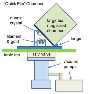 |
| Fig. 5. Small crystal coater. |
For many vacuum applications, the process is a cyclic one. The workload is placed in the chamber, the chamber is evacuated and the process takes place. The chamber is then let back up to atmospheric pressure and the process workload is removed. These cycles can be as short as a few seconds in the case of coating a small communications crystal (Fig. 5) to give it a specific frequency, or it can take several hours in the case of a heat treating cycle that may include evacuation, heating, soaking, cooling and eventually back to atmospheric pressure. In this type of cycle, the main “constituent” being removed is “air”.
However, “air” is a bit more complicated than it seems. Let’s look at what main gases are present in dry air, see Fig 6. There are two or three rare gases not included and the total will not add up to exactly 100%. In regular air that we breathe, there is also a small amount of water vapor. It varies due to the humidity at any specific place and can be from less than 0.01% up to over 5%. On average, at room temperature, it may be close to 1.57%.
Water vapor is lighter than most of the air molecules (nitrogen and oxygen) and the air can contain a percentage of moisture until it reaches its saturated vapor pressure, dependent also on temperature. If the water vapor content exceeds the saturated vapor pressure the excess moisture is given up outside in the form of rain or snow. Inside your home, you may see excess water vapor (humidity) as condensation on a cold window pane.
In the industrial or scientific world, similar phenomena exist inside the vacuum system. When we have a cyclic vacuum process and the chamber is opened to atmospheric pressure air, including dry gases and water vapor, enters the chamber. These very small invisible molecules are moving at very high speeds and are so densely packed together that they collide with each other and the surfaces inside the vacuum chamber many times each second. It is these collisions and the resulting forces that produce atmospheric pressure close to 14.7 psia (pounds per square inch absolute).
When “dry” air molecules collide with a surface they tend to stay on the surface for a very short time and then release off the surface in a completely random direction. The atomic bond between the molecule and the surface is very weak and the molecule easily moves away from the surface. At pressures near atmospheric pressure (760 Torr) the molecule will very quickly collide with other molecules due to the density of the air. This will be less than one ten thousandths of an inch. In this condition, the molecules are said to be in viscous flow conditions.
At pressures around 0.01 Torr (10 microns) the molecule may move about one-third of an inch before it collides with another molecule. As the pressure (and hence the density) is reduced in the vacuum system, the molecules will travel progressively longer distances before hitting other molecules or another surface. If the pressure is reduced further it becomes more likely that the gas molecule will collide with another surface inside the vacuum chamber rather than collide with another molecule. At this point and at lower pressures still, the gas molecules are said to be in molecular flow conditions.
So, from the above, most dry gas molecules are not much of a problem when we try to evacuate a vacuum system to run a process. Light molecules such as hydrogen and helium can be evacuated more slowly than the heavier molecules but they are rare in the air and do not generally create much of a problem. The main dry gas molecule that requires removal from the vacuum chamber is oxygen. Oxygen is reactive, can combine with other molecules and most importantly will promote burning if the process happens to include heat.
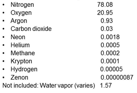 |
| Fig. 6. Gases in Dry Air (%). |
In the heat treating industry products can become oxidized if there are too many oxygen molecules present once the product is heated for processing. The vacuum pumps are used to reduce the percentage of oxygen molecules to a low level where they do not cause any problem. I’m sure many operators have seen oxidized parts come out of the furnace when something went wrong with the pump-down. The oxidation may be all over the product in the case of a major vacuum loss or it may be confined to certain areas of the chamber if a small leak developed during a process run.
Water vapor is the second constituent in the atmosphere that can create problems with your vacuum process. Water vapor has a stronger atomic bond than the dry gases and this causes water vapor molecules to “stick” to internal surfaces of the system long before they release and can be evacuated. If we boil water in a kettle on the stove at home, we have to give it the energy delivered by heating it to 212 degrees F before the water molecules have enough energy to release from the liquid and leave the spout of the kettle as steam. That is due to the 14.7 pounds per square inch of atmospheric pressure pushing on the surface of the water.
In the vacuum system, once the pressure is reduced by the vacuum pumps to about 18 Torr, water molecules on the surface of the chamber interior will release or evaporate from the surface at about 68 degrees F (room temperature) and be pumped away. This is why on many large vacuum systems Roots boosters or Roots blowers are used in this pressure area. In a somewhat short period of time, as the pressure reduces through the 50 to 5 Torr region, a large volume of water vapor is released from the chamber and product surfaces inside the chamber and need to be evacuated (pumped away) quickly. The Roots booster pump is designed to operate in this pressure area and has a high pumping speed. It can evacuate the large volume of water vapor and pass it on to the roughing pump to be exhausted back to the atmosphere.
If the vacuum system uses heat as part of the process, the chamber can be preheated to give the water vapor more energy and encourage it to release off the surfaces. Clean and smooth surfaces are preferred inside the vacuum chamber but not always possible. Materials inside the chamber that are porous should be avoided, this type of material may have a tremendously large surface area due to the small holes in it, will adsorb water vapor when the chamber is open and is slow to release the water vapor. Some insulating materials may have this type of texture.
In humid weather, large vacuum coating systems are particularly prone to capturing moisture unless the chamber is kept very clean. This is true especially for systems evaporating aluminum onto metals of plastics that may run a complete cycle every hour or so. Layer upon layer of coating material tends to adsorb moisture and cause the evacuation to take longer to reach process vacuum. Using liners inside the chamber walls is a way to reduce this problem, they will receive a major portion of the contamination and can be changed out for clean ones once the pump down time becomes extended. The clean liners will allow for a faster pump down while the contaminated liners can be cleaned in preparation for the next change over.
Some vacuum systems use cold traps to capture this water vapor before it reaches the oil-sealed vacuum pump, as the lowest pressure attainable by the vacuum pump will be compromised if water vapor condenses in the oil. Cold traps work well but do require some service/maintenance to eliminate any trapped moisture either each cycle or perhaps at the end of a shift. Another option to reduce the amount of water vapor condensing in the vacuum pump oil is to use the gas ballast valve during the time that the water vapor is being pumped and perhaps additional gas ballasting between cycles to help keep the oil clear of water vapor contamination.
In vacuum systems that utilize glass bell jar chambers, it is not unusual to see a cloud of water vapor for a few milliseconds at the point where the water vapor evolves from the internal surfaces.
In conclusion for this section, cyclic systems, the main “enemies” of the process are oxygen and water vapor.
Continuous vacuum processes.
 |
| Fig. 7. Inline Vacuum System. |
This type of system has different problems when it comes to removing active and reactive constituents. Some systems can be in-line load lock systems and the center chamber or chambers stay under vacuum once the whole system is started up. Others may have multiple load lock and process chambers with a central automatic robot arm to move the product from one chamber to the next. This type of “cluster tool” is commonly used for processing silicon wafers that will eventually have many integrated circuits (computer chips) build upon them.
In line vacuum process systems
The in-line systems, Fig. 7, have load lock chambers that are used to move the product being processed into and out of the process chambers. They act in a similar fashion to the cyclic systems above but see many more air to vacuum cycles. In fact, the pumps needed for load lock operation need to be selected carefully as they see frequent high pressure (atmospheric pressure) loads and that tends to make the pumps operate hotter than when mostly operating at low pressure. These systems can require an evacuation from atmospheric pressure to vacuum every two or three minutes which is tough on the vacuum pumps and they often need additional maintenance due to the difficult application. Each load lock and each process chamber will have its own set of vacuum pumps. In Fig. 7 the work racks or work holders may be on a looped track so that once unloaded they return to the inlet end to be reloaded for the next cycle.
The process chambers themselves, however, don’t see atmosphere once they are evacuated to the operating pressure and start the process. These systems often have gases bled into the process chamber as part of the process. These gases create a chemical reaction on the substrate and then the reacted gases have to be pumped away quickly by the vacuum pumps ready for the next process load entering through the load lock. Other processes may create solid effluent in the form of fine dust and this is evacuated towards the vacuum pumps. Oil sealed pump sets may use inlet traps to catch this contaminant before it reaches the pump or dry pumps may be used and the contaminants captured after passing through the pump mechanism.
Semiconductor processing tools
As stated above, cluster tools consist of a number of process chambers mounted around a central vacuum chamber called a transfer chamber. Each chamber will have its own vacuum pumps and may operate at different vacuum levels depending on the specific process. The load locks are fitted with a vacuum gate valve on the entry from outside and another to allow the load to be presented to the robot arm in the transfer chamber. A load may consist of a special wafer holder called a cassette that holds twenty-five silicon wafers. The cassette may stay in the load lock but the inner gate valve is open to allow the robot arm to select a wafer and move it to the first process chamber. Each process chamber will be fitted with a valved entry to allow the robot arm to place a wafer inside it for processing and then remove it and deliver it to the next process chamber in turn.
| Fig. 8. Semiconductor “cluster tool”. |
Not shown in Fig. 8 are the larger dry pump/Roots pump sets that are situated in the basement under the tool. These tools require so many pumps that they are often stacked two high to save space. In the last few years, manufacturers have started to use variable frequency drives to allow the pumps to run faster when needed. This has allowed the footprint of the pumps to be smaller and also reduces power requirements. This type of tool has very clever controls to make sure every step of the process in each chamber is done correctly. Thank goodness for computer controls!
From inside the clean rooms a semiconductor manufacturing facility “fab” looks very pristine. All the operators are wearing bunny suits, hair coverings, and booties. But, as the processes take place on the wafers – a number of coating and etching steps – there is a lot of dangerous gas mixture effluent being exhausted by the vacuum pumps. The inside of the process chambers, vacuum lines, vacuum pumps and even the exhaust lines are filled with gases that may kill you if you breathe them, may burst into spontaneous combustion if they see oxygen, can condense into solids and block the pipelines and probably several other nasty results that are not mentioned.
Hazardous gases used to create chemical reactions include silane, arsine, phosphine, nitrogen trifluoride and tungsten fluoride.
The vacuum pumps have to take the nasty mixtures of reactive gases and compress them through the pump mechanism and exhaust them to the exhaust abatement equipment. In many cases, this effluent is so dangerous that it has to be chemically reacted to safe gases and/or incinerated before it can be exhausted back into the atmosphere.
In the case of condensable vapors, it is sometimes necessary to run the vacuum pump at a specific temperature and heat the vacuum lines to prevent the condensable vapors from solidifying. Many semiconductor processes that use chemical reactions to coat wafers and then etch materials away in another chamber use inert nitrogen purges. The nitrogen doesn’t react with the dangerous chemical mixtures but protects the inner pump surfaces from corrosion, helps to blow the solid contaminants through the mechanism and dilutes the gases to less hazardous mixtures.
In conclusion, for continuous processes, the vacuum pumps remove the process gases from the chamber ready for the next process step and are also tuned to suit the specific gas mixture that is being reacted.
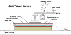 |
| Fig. 9. Vacuum Bagging (for composites) |
3. To Remove Trapped and Dissolved Gases
Trapped Gases
In a typical industrial vacuum system, it is possible to trap pockets of atmospheric air when manufacturing the system and each time a cyclic system is unloaded and reloaded. One example is fixtures that are bolted to brackets on the chamber wall. If the securing bolts are placed in blind tapped holes, gas can be trapped in the bottom of the hole. With a regular bolt in a blind tapped hole, the only escape for gas molecules is along the thread form where there is space in the root and crown areas of the thread. If a blind hole is unavoidable, bolts that have a hole through them will allow the air to escape easily during the evacuation part of the process. There is a company in the USA that specializes in these types of bolts and screws. Using tapped through holes eliminates this problem.
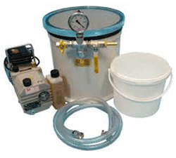 |
| Fig. 10. A small urethane degassing system |
If a fixture is held in place with a bolt and a nut or nut and washer, air can be trapped in the space around the bolt in the clearance hole. Again the air will slowly bleed away during the evacuation and extend the pump downtime. Even mating surfaces can trap air under them which will cause a slower evacuation because the trapped air will only release slowly.
Another example of trapped gases in the heat treat industry is when porous insulation materials are used. Air will be adsorbed into the porous material, which has a very large internal surface area, at atmospheric pressure and will then be slow to release during the evacuation due to low conductance of gas from the very tiny spaces in the material.
In the refrigeration and air conditioning industry small bore tubing will have water vapor adsorb onto the inside of the tubes during manufacturing or when assemblies such as cooling coils are stored in the shop. This water vapor must be removed after assembly and before the refrigerant is charged into the system. Any water vapor not removed may be enough to freeze at the expansion valve and cause the system to stop working. The process of expanding the refrigerant uses heat which causes the refrigerator to get cold or the air conditioner to cool the air blown over its coils. Any water in the refrigerant will freeze at the point where the expansion takes place and block the flow. Every time a refrigeration device is serviced it has to be dehydrated before the new refrigerant is added.
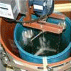 |
| Fig. 11. Degas system with motor-driven impeller |
This water vapor is said to be trapped because it is difficult to remove it easily and quickly. By evacuating the tubing the water vapor slowly releases off the interior surfaces and is pumped away. Water has a vapor pressure of about 18 Torr at room temperature. This process can take several hours due to low flow conditions (low conductance) inside the small bore tubing at low pressure.
A process called Vacuum Bagging is used to remove vapors and condition fiberglass and other layered composite material moldings. The layers of material can trap bubbles of air and vapor is given off the wet materials as they cure. It is used to make composite items for boats, airplanes, cars, bicycles and many other products where strength and light weight parts are needed. The “layup” of materials to be vacuum bagged is covered with a porous material and then with a rubber or plastic cover which is sealed at the edges. The porous material allows the trapped air and vapors to move through it to reach the one or more vacuum connections in the pliable bag and be pumped away. This process can take days to complete, depending on the size of the layup and the materials used. Fig. 1 shows a cross-section through a typical vacuum bagging layup.
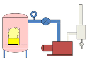 |
| Fig. 12. A simplified Urethane Degassing System |
Note that vacuum is also used for drying products such as sterilized medical items, some foods, and industrial parts after wet processing. Another drying process called freeze-drying is used for drying temperature sensitive products such as vaccines, flowers, and other foods. In this process, the product is pre-frozen and then placed under vacuum. In the vacuum, the ice will “sublime” to water vapor without going through the liquid phase. The water vapor is collected on a cold condenser located between the main chamber and the vacuum pump. These processes may also be classified as “Reason 2, Removing Active and Reactive Gases”.
Dissolved Gases in Liquids
Vacuum Degassing
A number of liquids are used in industry for different applications and they generally need to be pure or the process may be affected. During mixing and pouring operations gas can be trapped in the liquid as small bubbles. Some bubbles of gas may be visible and others may dissolve into the liquid and be invisible to the naked eye.
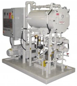 |
| Fig. 13. Transformer Oil Dryer and Degasser |
Urethanes are often used for small molded products such as plugs, caps/covers, grommets, bumpers and even tires for forklift trucks. Bubbles of gas in the first four items will make them appear to be of poor quality. Bubbles in the forklift truck tires may cause accelerated wear and a shorter life.
Resins are used for casting parts and decorative figures as well as for potting small electronic components. A company I once visited was molding Dungeon and Dragon figurines.
Single-stage rotary vane vacuum pumps are often used for degassing urethane and other somewhat viscous liquids prior to pouring them in the mold. The product will degas once the vacuum is below about a half-atmosphere (380 Torr) depending on the viscosity of the liquid. The amount of liquid degassed at one time can vary from a few ounces to many gallons depending on the product but the process is quite similar.
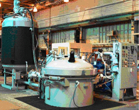 |
| Fig. 14. Large Vac./Press. Impreg. System |
A small molding system is shown in Fig. 10. In this system, a container with urethane in it would be placed in the vacuum chamber and the acrylic lid replaced on top. The see-through lid lets the operator watch the process and control how fast it degasses. Degassing resin, varnish and urethane can result in a lot of frothing. As the gas bubbles in the liquid move to the top of the liquid, expand and burst they release the trapped gas into the chamber where it is evacuated by the vacuum pump. To reduce the frothing the rate of pressure drop is controlled by a valve such as a ball valve in the vacuum line outside the chamber. Due to the frothing, the container holding the liquid often has a high depth to diameter ratio so that the frothing doesn’t spill out of it. After the first high rate of frothing has diminished the operator can visually see when there is no more gas escaping from the product.
In larger systems with gallons of liquid to degas, a stirring mechanism is often added to the chamber to slowly move liquid from the bottom of the chamber to the top. The gas bubbles will escape from the liquid easier when they are near the top of the liquid with less weight of liquid pressing on them. The chamber shown in Fig. 11 has a 55-gallon drum loaded in it and a motor driven stirrer mounted through the lid. Fig. 12 shows a line drawing cross-section through a typical urethane degassing system.
 |
| Fig. 15. A simplified Vacuum Impregnation System |
To prevent arcing the special oil used in electrical transformers is degassed to remove entrained air and absorbed moisture before it is used to fill a transformer case. (Fig. 13) The system heats the oil uniformly to help moisture to evaporate and then sprays it over a series of thin metal plates in the chamber to degas. The oil runs over the plates in a thin film which improves the efficiency of the degassing.
Vacuum and Pressure Impregnation (VPI)
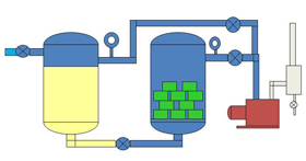
Varnishes and resins are used for potting and also for insulating items such as electric motor and transformer windings. The liquid is degassed and then used in a two chamber unit called an impregnation system (Fig. 14). The windings are placed in a vacuum chamber and placed under vacuum. Molecules of air are trapped between the layers of copper wire and it takes some time for this air to escape from the small spaces and be pumped away. Once the air is removed the liquid is introduced to the vacuum chamber from a storage vessel. With the air molecules removed the liquid is able to penetrate every small space between the windings and create a layer of insulation. A positive pressure is applied to the top of the liquid to help force the liquid into the tiny voids. Fig. 7 shows a typical VPI system.
Many metal castings often have voids in them when they solidify. These castings are often impregnated with liquid resin to seal any porosity and imperfections. Once the casting is impregnated it is heated to cure the resin. The process is similar to VPI described above and is especially important in the automotive engine industry to seal aluminum casting.
4. Vacuum used to Decrease Thermal Transfer
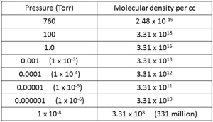 |
| Fig. 16 Molecular Density at different pressures. |
If you commute to work by car and your drive is an hour or so, you may well take a coffee or another hot or cold beverage in your own personal container to drink on the way. Often this type of container is a vacuum insulated cup with a lid. A step up from that, if you work on a job site for example, would be a vessel that holds several cups of liquid for all day use. You may know these as “Thermos” or “Aladdin” flasks which are two of the trade names for vacuum insulated containers.
Let’s discuss the thermodynamics of vacuum insulated vessels and then look at other uses for them.
Gas molecules
Air at atmospheric pressure, 760 Torr or 1013 mbar, contains about 25 million, million, million molecules in each cubic centimeter of volume (Fig.16). This volume can be visualized as being similar to that of a sugar cube or a die. These molecules generally move in straight lines until they either collide with each other or with a surface. They move at a speed of about 1000 miles per hour. At higher pressure such as atmospheric pressure, they are more likely to collide with another molecule and will move off in another direction until the next collision. Each molecule will travel only about 2.5 millionths of an inch between collisions at atmospheric pressure. (Fig. 17)
If the molecules are inside a chamber at atmospheric pressure, some molecules will collide with the inner surface of the chamber and any work holders or fixtures. When that occurs, the molecule typically resides on the surface for a fraction of a second and then releases and moves away from the surface in a completely random direction.
There will be different results if the chamber wall is either heated or cooled. If a molecule hits a cooler surface it will lose some of its heat to that surface and may have less energy available to release off the surface. In some cases, it may adsorb onto the surface if it loses most of its energy. On the other hand, if the surface is warmer it will gain energy and will release with increased energy.
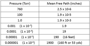 |
| Fig. 17. MFP at different pressures. |
So, as these gas molecules are moving randomly around the vacuum chamber they can be constantly gaining or losing energy, depending on whether they collide with a hotter or cooler molecule of the surface. From that, we can state that “Heat is transferred by molecular collisions”.
Molecular Density
If we think about the last statement, we can conclude that if there are fewer molecules in the closed vessel, there will be less heat transmitted due to fewer molecular collisions.
That leads us to consider molecular density. How many molecules are there in unit volume at lower pressures than atmospheric conditions? A few examples are shown in Fig.16, starting with 2.48 x 10¹⁹ molecules per cc (that is 25 million, million, million) at atmospheric pressure of 760 Torr. These guys are very tiny.
At a typical vacuum furnace pressure of between 10-5 and 10-6 Torr there are still about 33 thousand million to 330 thousand million molecules of gas in each cc of volume. It’s not until the pressure is reduced to around 10-10 Torr, ultra-high vacuum, that the number of molecules comes down to the 3 million per cc range.
The pressure on the moon’s surface is around 10-12 Torr and at that pressure, there would still be about 33,000 molecules per cc. Even in outer space (10-22 Torr), and we know from the science shows that there are gas clouds out there, physicists estimate that there are around 4 molecules of gas in every cubic meter of volume.
As the density of the molecules is reduced as the pressure drops, the distance between the individual molecules increase. There are fewer molecules in the volume so they must move a longer distance before colliding with another one. This distance will vary, so the physicists have another term, mean free path, to average the distances for comparison.
Mean Free Path
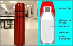 |
| Fig. 18. Thermos flasks for hot or cold liquids. |
Mean Free Path is the average distance a gas molecule will move before it collides with another molecule, at a certain pressure. I’m not sure how this is done with tiny molecules that can’t be seen. (It is another part of the wonders of science that have slowly been discovered over the last couple of hundred years or so.) See Fig. 17.
At higher pressure,s the Mean Free Path is very short and the molecules collide frequently. The MFP is 2.5 millionths of an inch at 760 Torr. As the pressure is reduced to 1 Torr the MFP is has increased to about 2 thousandths of an inch, a movement that we can relate to in engineering. As the pressure reduces to the level that a combination of an oil-sealed rotary piston vacuum pump and Roots booster can reach (0.001 Torr or 1micron) the MFP has increased to about 2 inches.
If those molecules are in a part of the system larger than about 6 inches diameter, they are still moving in a viscous flow. Meaning they are more likely to collide with another molecule than with the vessel wall. If however, the molecules are in the holding pump piping (usually a 25mm line) they will be moving in molecular flow; meaning they are more likely to collide with the inner wall of the piping than with another molecule.
As the pressure drops to about 10-5 Torr the MFP has lengthened to about 16 feet. For most average sized vacuum furnaces that means that molecules of gas inside the vacuum chamber are much more likely to collide with an interior surface of the chamber than with another gas molecule.
Now the physics is explained, let’s talk about the application, vacuum as an insulator.
Vacuum Insulated Vessels.
This type of vessel can vary from small “low tech” insulated coffee flasks to large liquid nitrogen storage tanks and the trailers that deliver the bulk liquid to them. In between are many different shapes and sizes of vacuum insulated containers, some called Dewars, and also installed systems where connection pipelines have to be vacuum-insulated as well.
Typical insulated flasks for hot and cold liquids look like the one shown in Fig. 18. Although Sir James Dewar invented what is known as the Dewar flask, he never patented it. Two Germans discovered its use for commercial purposes and registered the name Thermos in 1904. The Thermos company still exists today although they have many competitors.
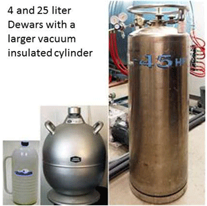 |
| Fig. 19. Lab and hospital sized Dewars. |
Vacuum insulation is used because it works well and as long as there are no leaks, the item will last for many years. It is mainly used where the temperature difference between the outside and the inside of the vessel is large and many scientific and industrial applications involve cryogenic liquids.
One of the most popular cryogenic liquids, liquefied gases, is liquid nitrogen. It is usually written as LN2. Liquid nitrogen has a boiling point of -196°C (77°Kelvin) or -321°F. Safety precautions must be taken when handling any cryogenic liquids. They will burn skin and damage your eyes. Gloves and a face mask are required if transferring any cryogenic liquid into or out of an open Dewar flask or other suitable vessels.
Dewar’s first container was made of metal, but two containers of glass joined together and sealed under vacuum proved to be a very effective improvement. Obviously, glass containers are fragile, and the glass used is quite thin, so care must be taken not to drop or bang them which could break the glass. The vacuum between the two glass vessels reduces heat conduction and convection, and the glass is “silvered” to reduce thermal radiation. The silvered surface reflects heat and is often a coating of evaporated aluminum. (Another vacuum process!)
The laboratory-sized Dewars, Fig. 19, are typically made using thicker glass and layers of additional insulation inside the metal or plastic container. These can be carried by hand or on a small cart. The small Dewars shown are typically purchased by the end user and filled in-house from a larger container such as the larger cylinder shown. The larger cylinder would only be handled by a qualified technician due to its weight and value. These vessels are evacuated to the 10-5 Torr region using either turbo or diffusion pump systems, and then left to pump for another 48 hours (Ref. 3). Gas flow through the insulation layers is slow and it takes a while to reach the vacuum level required throughout the whole interspace.
Although the large gas companies such as Air Products, Linde and Air Liquide produce these cryogenic liquids, they have mostly let the distribution of these smaller volumes be carried out by companies such as AirGas and other smaller local distributors. They have a regular schedule of deliveries so that labs and hospitals are never without product.
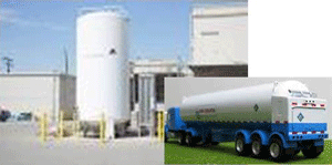 |
| Fig. 20. Large storage tank and road trailer. |
The large gas companies look after the large volume storage tanks that have to be refilled by trailer loads of product, Fig. 20. These vessels are very heavy, and the inner vessel requires substantial supports between it and the outer vessel to provide strength, support, and the correct spacing. The annular vacuum volume is filled with layers of aluminized material and also Perlite. Perlite is a material similar to natural glass. When heated it expands to between 4 and 20 times its original volume with lots of voids in its structure. It is a good insulator and resists crushing. Literature suggests that Perlite can settle, especially in a vessel such as a road tanker that is subject to vibration over a long period of time. This problem can allow more heat transfer towards the top of the trailer and may result in a higher “boil off” rate of the LN2 or other cryogenic liquid in the tanker. If too much product is lost by boiling off, this is an additional cost to the gas company and the trailer may have to be serviced.
In Fig. 20 you can see the road tanker has a closed area at the rear of the trailer. This is where the valves and piping are to allow for connection to the customer’s storage tank that is being refilled. In this area would also be a vacuum gauge head on a gauge head connection, to allow the interspace pressure to be checked as needed. The vacuum gauge typically used for this is a battery operated thermocouple gauge. This gauge actually reads the temperature of a hot filament in the gauge sensor, but instead of reading it in degrees of heat, it reads it as an equivalent vacuum reading.
The hot filament changes temperature as the vacuum level changes. When the pressure drops in the sensor there are fewer molecules of gas to take heat away from the filament, so it gets hotter. This change can be calibrated to indicate the pressure. When you see these large tank trailers on the highway please allow them plenty of space. They carry a precious and valuable cargo. The gas companies only allow their very best driver/operators to deliver cryogenic liquids.
 |
|
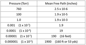
Fig. 21. MFP at different pressures
|
5. To increase the Mean Free Path to a useful dimension
The gas state
The article printed back in January this year talked about solid, liquid and gas states of matter. The following is a short excerpt from that article.
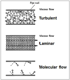 |
| Fig. 22. Flow of Molecules |
“In a gas, the atoms and molecules are generally much further apart than in solids and liquids. In air at atmospheric pressure and room temperature, the actual space occupied by atoms and molecules is about 0.01 percent or one ten-thousandth of the volume. The equivalent for solid copper is about 74 percent or close to three quarters. (So much for being called a “solid”).
In air, the molecules are in constant random movement, typically in a straight line, and the interatomic forces have little effect due to the space between the molecules. The moving molecules will constantly collide with other molecules and then move away in a different direction. These collisions occur about 10,000,000,000 times per second at atmospheric pressure.”
Atmospheric pressure is always the starting point of any vacuum process, and we know that we can reduce that pressure in a closed vacuum chamber by using one or more vacuum pumps to reach whatever lower pressure (vacuum) is required for the process.
 |
| Fig. 23. Conductance in Pipes |
In the excerpt above it states that molecules in the chamber are constantly colliding with other molecules and changing direction. Molecules of gas that collide with the inner chamber wall, or the surface of any fitment, work holder or product in that chamber will reside on that surface for a fraction of a second and then release off the surface in a completely random direction.
Mean free path
The term “mean free path” is the average distance that a molecule will move before colliding with another molecule, it is measured in inches or meters and is related to the pressure and density of the gas molecules in the chamber. We usually show the mean free path at a certain pressure because that is how we measure the vacuum level using some type of vacuum gauge (Fig. 21). Density is related to the pressure but is rarely used as an indicator for vacuum processes.
From Fig. 21 we can “see” that as the pressure in the vacuum system drops the mean free path becomes longer. Molecules of gas are being evacuated by the pumps, the density of the gas is being reduced and the molecules have to move further before they collide with another molecule. I used the word “see” above but this is one of the most difficult things about understanding what is happening in a vacuum chamber, you can’t actually “see” the molecules.
Quick review of conductance
 |
| Fig. 24. Vacuum evaporation coating |
The increase in the mean free path of gas molecules starts to become useful once it reaches several inches, but just before that point, there is another interesting occurrence. This is the transition of the flow of molecules in the vacuum system piping from viscous or continuum flow to molecular flow (Fig. 22). This drawing tries to show the changes in the flow of molecules moving down a pipeline as the pressure is reduced. It is simplified and does not show the flow variations at the pipe wall, however, the reader will see these main differences.
When I delivered vacuum technology classes for Edwards I likened the changes to the crowd leaving a stadium at the end of a football game. (It assumes that the game kept the crowd in their seats until the end!)
Viscous flow, turbulent: When the final whistle blows most of the crowd attempts to move towards the exits and there is a lot of random movement as the crowd jostles around trying to move into any open space that may lead to a faster exit.
Viscous flow, laminar: After a few minutes the big rush has moved away and the rest of the crowd has more room to move in an orderly fashion towards the exits.
 |
| Fig. 25. Electron beam gun |
Molecular flow: A bit later most of the crowd has left and the remaining few can meander all over the walkways going in a variety of directions without being jostled by anyone else.
Returning to the molecules, the big change in all this occurs between laminar flow and molecular flow, when the mean free path becomes longer than the inside diameter of the pipe. At and after that point the gas molecules are more likely to collide with the walls of the pipeline (or chamber) than collide with another molecule.
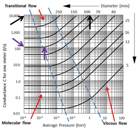
This change also affects the conductance in the pipeline. Conductance is the measure of the mass of gas flowing at the average pressure per meter of pipe length. It is measured in liters per second, per meter (Fig 23.). This graph shows how the conductance changes in a number of different diameters of pipe as the pressure changes. The interesting point to see is that as the pressure drops the conductance also drops until the gas flow changes to molecular flow. Once the molecules are in molecular flow the conductance becomes constant.
For example, look at the curve in Fig. 23 for a 100 mm diameter pipeline. At a pressure of about 1 Torr the conductance is 10,000 liters/sec and steadily drops as the pressure drops. However, at around 0.002 Torr (2 x 10⁻³ Torr) the conductance becomes constant at about 100 liters/sec and does not change as the pressure drops below that reading.
Vacuum applications due to a long MFP
 |
| Fig. 26. Sputter coating process |
Going back to the discussion of “mean free path” there are a number of processes that become viable once the MFP is longer than a few inches. The reason is that once the MFP is relatively long, other small objects can move across the vacuum system with a good chance of not colliding with a gas molecule. If, for example, the vacuum chamber is at a pressure of about 0.00001 Torr (1 x 10⁻⁵ Torr) the MFP will be around 190 inches or 16 feet. If the vacuum chamber has a diameter of only 5 feet it is unlikely that a molecule of gas will strike another when it moves across the chamber.
This allows systems such as vacuum coaters, electron microscopes, mass spectrometers, surface science instruments and particle accelerators to work successfully. Let’s see how each of these works under low-pressure conditions.
Vacuum coating
Vacuum coating or vacuum deposition is a method of producing a finish coat on a substrate. The substrate may be paper, metal, plastic, glass or some of the fancy materials used in the manufacture of integrated circuits (computer chips). The actual deposition process is selected depending on the substrate material, the material being deposited, the thickness and surface finish of the coating and whether the substrate is stiff or flexible. They are only successful processes because the material being deposited can move across the space without colliding with a gas molecule.
Typical deposition processes are:
 |
| Fig. 27. Electron beam microscope |
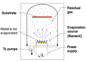
Evaporation by a hot filament (Fig. 24)
In this process metal is evaporated from a hot wound filament or boat filament. The wound filament is used for solid metals where small sections of wire are placed over the filament loops. Boats are used when the metal is in powder form. In both cases the metal vapor evaporates in straight lines and condenses on the first surface it touches. The item being coated (substrate) is placed at a suitable distance from the filament so that coating is as even as needed. If multiple parts are being coated they would be placed in a work holder. This process tends to contaminate all interior surfaces of the chamber in line of site with the evaporation material. Shields are often used so that they can be replaced or cleaned when the contamination builds up and makes the pumping cycle longer.
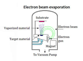
Evaporation using an electron beam gun (Fig. 25)
This system is also used for coating metals but the material is melted by a high powered beam of electrons emitted from the filament. This is often a longer process and the filament is protected from contamination by placing it under the water-cooled crucible that contains the material being evaporated. A magnetic field bends the beam of electrons through 270 degrees and onto the material. The beam can be focused and also moved across the metal in the crucible to melt it somewhat evenly.
 |
| Fig. 28. Picture from an electron beam microscope |
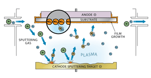
Sputter coating using a plasma (Fig. 26)
Sputter coating is a more difficult process to understand. In this process, the material being sputtered and the substrate are arranged as a cathode and anode. Argon gas is bled into the vacuum chamber and is ionized to produce a plasma between the two electrodes. The argon ions are accelerated into the cathode material, called the target, and they dislodge particles of the target material. The dislodged material is then attracted to the anode to which the substrate is attached to and creates a coating on the substrate.
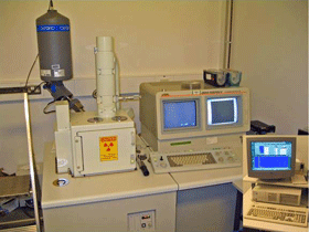
Electron beam microscopes (Fig. 27)
These instruments are used to look at items and surfaces under very high magnification. Electrons are fired from an electron gun and are either scanned over the item surface or transmitted through the surface. Please consult an expert to learn about the differences, I have only a simple knowledge of these instruments as it is the vacuum pumps that are my concern. Fig. 27 shows an electron microscope and you can see the white vertical column in the center which is the electron beam assembly. The electron gun is at the top and the item to be viewed is in the cube-shaped chamber below it. The white column has to be evacuated to a low enough pressure that the mean free path of remaining gas molecules is substantially longer than the height of the column. This would generally be a turbomolecular pump and mechanical pump combination. The picture in Fig. 8 shows the head of a fly in great detail.
 |
| Fig. 29. Mass spectrometer |
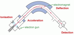
Mass spectrometers (Fig. 29)
It was difficult to find a simple picture of how a mass spectrometer works. It is a device to determine (analyze) what a gas or solid is made of by ionizing a small sample. There are two main types of mass spectrometer; one that uses gas chromatography, a GC-MS, and the other that uses liquid chromatography, an LC-MS. Again, this is not my area of expertise; consult an expert for more information. Both types of Mass Spec ionize the sample and separate the ions by magnetism so that the detector can determine what the constituents are. The different constituents are displayed on a screen by mass number. The whole detection system is under vacuum and only works because the ions do not collide with any gas molecules in the chamber under vacuum.
Other applications
There are other applications using low-pressure conditions to allow ions, electrons and other small particles to move through a system without colliding with gas molecules. Surface science systems are one of these and physically large systems such as particle accelerators are included. The CERN accelerator in Europe has a circular vacuum chamber that is about one meter in diameter cross section in an underground circular tunnel. The circle itself is about 9 kilometers across.
Each of these applications is a much more complicated science than I have tried to explain in this short article. I hope it has “tweaked” your interest.
References
- The chart in Figure 5 is from “Modern Vacuum Practice” written and published in the UK by Nigel Harris.
- The three-dimensional representation of a cluster tool in Figure 8 was modified from a slide in a BOC Edwards presentation. (BOC Edwards is now Edwards Vacuum, a division of Atlas Copco.
- Bryan Oliver, Cryotec, Inc., Indianapolis, IN.
Copyright Howard Tring, Tring Enterprises LLC Vacuum & Low-Pressure Consulting.
