When a vacuum system is designed it is often necessary to select a mechanical vacuum pump or pump set that will evacuate the chamber and associated piping in a certain amount of time. In laboratory or research situations that may not be as necessary as in a production environment where the time to complete a process has quite a lot to do with the cost of the manufactured part. In addition, the cost of the vacuum system has to be taken into consideration as well. Larger pumps may reduce the evacuation time, but also are more expensive. There has to be a balance between all the parameters.
There are two simple methods for calculating evacuation time; one for a rotary vacuum pump, vane or piston, on its own, and a second for larger volumes when a vacuum booster pump may be used. Both methods give good results for simple vacuum systems where the mechanical vacuum pumps are located close to the chamber and the chamber is relatively empty.

Evacuation time using a mechanical rotary vane or piston pump
The simple formula used for this calculation is: T = V / S F
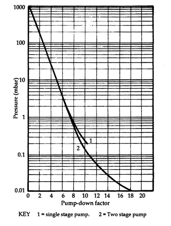
Where T is time, V is volume, S is pumping speed and F is a pump down factor taken from the graph shown in Fig.1. The units used should be consistent, i.e. Time in minutes, Volume in cubic feet and Speed in cubic feet per minute (cfm). You can also use liters for Volume if you use liters per minute for Speed.
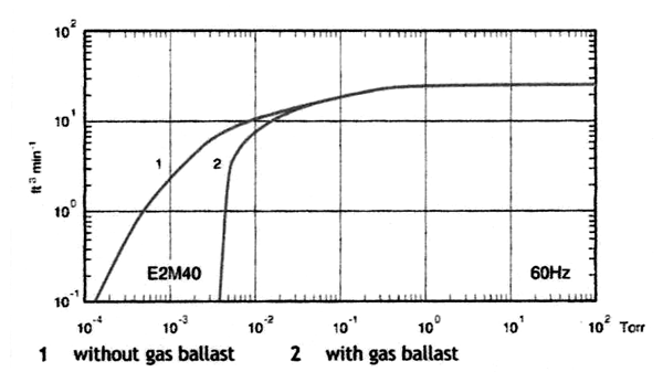
This simple formula works because the pumping speed versus pressure curve for a rotary vane or piston pump is fairly flat until the pressure reaches around 10 Torr and then it drops in a smooth curve as the pump loses efficiency at lower pressures. (Fig.2)
Pumping speed for mechanical vacuum pumps is usually stated in cubic feet per minute or liters per minute units and can be taken from the manufacturer’s literature. Make sure that you use actual pumping speed rather than displacement to see the best results, and in North America check that these numbers are when the pump has a 60 Hz electric motor.
Example 1.
Using this formula calculates the pump downtime T, to reach a vacuum level of 0.1 mbar (0.075 Torr or 75 microns) if the chamber volume is 150 cubic feet and the existing vacuum pump speed is 150 cfm.
First, we need to find the pump down factor F, from the graph in Fig.1. Reading across the 0.1 mbar line on the graph it crosses the curve between 10 and 12, so let’s say F = 11 to always err on the plus side. Note that the curve indicates a two-stage vacuum pump is needed. Now we can put the numbers into the formula and find the time required.
T = V / S F becomes T = 150 / 150 x 11 and T = 11 minutes (approximately)

Remember that this formula assumes a clean, open, vacuum chamber and short connections to the pump.
So, in this example, the estimated roughing time to evacuate the chamber is eleven minutes. That may be acceptable for the application or the designer may want to reduce that time by using a larger vacuum pump or allow for a real-life slower pump down due to fixtures in the chamber, product in the chamber and or piping from the chamber to the vacuum pump extending eight or ten feet. If the designer wanted to reduce that evacuation time, using a 300 cfm vacuum pump would cut the time in half.
Then in actual conditions, using the larger vacuum pump, when flow restrictions, surface outgassing, leaks, and conductance losses are taken into consideration, the evacuation time should still be better than the original 11 minutes.
Evacuation time using a Roots booster combination pump set
Another pumping option to evacuate large volumes is to add a vacuum booster pump to the mechanical rotary pump. The combination of these two vacuum pumps works extremely well for two reasons. The vacuum booster pump (often called a blower) has a very high pumping speed around the vacuum level where water vapor evolves from the system surfaces and it also reduces the chamber pressure by about one decade.
For evacuating vacuum chambers a Roots booster pump requires a mechanical backing pump. The average compression ratio of a Roots booster alone is only around 20:1. This is not efficient enough to create low pressure in the chamber on its own. 760 Torr divided by a factor of 20 would only create a pressure of around 38 Torr. A combination of the two pump designs is ideal because the Roots booster has a very high pumping speed and the mechanical oil-sealed pump has a high compression ratio. (2-stage oil-sealed rotary vane pumps have a compression ratio of 50,000/1 or higher) The combination allows a fast evacuation time and a low enough pressure to be created that the oil diffusion or other secondary pumps can start to operate safely.
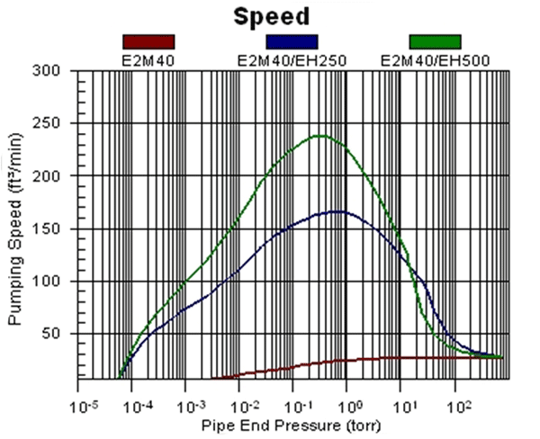
The pumping speed against pressure graph for a vacuum booster pump is not a smooth curve. The graph varies from manufacturer to manufacturer even though the pump design is based on the original Roots design. The pump speed curve is similar to a bell-shaped curve and rises to a peak from startup and then drops off as the pressure drops. (Fig. 3)
These pumps are used in the evacuation of large volumes because they have their highest pumping speeds between about 50 Torr and 0.01 Torr. This, as stated above, is where most of the chamber surface water vapor will evolve and required a high pumping speed to pump it out of the system. The vapor pressure of water at room temperature is around 18 Torr, so the 50 to 0.01 Torr range covers that area well.

Because the main function of the Roots vacuum booster, or Roots blower, is to evacuate this water vapor, the electric motor is sized to handle the required workload in that pressure area as well. This means that the vacuum booster pump is not started until the chamber pressure has been reduced enough that the electric motor will not be overloaded. Making sure that the booster motor is not overloaded when pumping at higher pressures can be done in three ways.
1. By using a pressure switch that starts the booster pump at the correct pressure
2. By having a spring-loaded bypass valve to recirculate the gas, and
3. Incorporating a fluid coupling into the drive that slips at higher pressures
Due to the shape of the booster pump curve, a different method of calculating evacuation time is used. This formula is:
T = 2.3 (V / S) log10 (P1 / P2)
Where T is time, V is volume, S is pumping speed and P is pressure. Again the units used must be consistent.
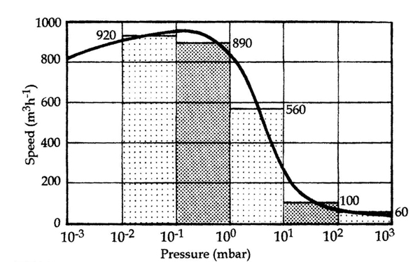
In this case, because the pumping speed varies, we have to calculate the time required for each decade of pressure across the curve. This makes the formula very simple because log10 (P1 / P2) becomes 1. (Each P1/P2 = 10 and log10 (10) = 1)
That leaves T = 2.3 (V / S) per decade. We can select an average speed per decade from a booster pumping speed curve as indicated in Fig. 4. Calculate the time for each decade we need to include and then add them up. (Note: Fig. 4 is not the actual pump speed curve in example 2 it is only to show the decades of pressure.)
Example 2.
Taking the same chamber volume, 150 cubic feet, as in example 1 let’s see how the evacuation time compares.
Using the top curve in Fig. 3 for the E2M40/EH500 booster combination the estimated average pump speeds are needed for four of the decades, down to 0.1 Torr. (It was 0.1 mbar in example 1 but the time difference will be small)
The average pumping speeds estimated for the four decades starting from atmospheric pressure on the right-hand side of the graph (Fig. 3) for the E2M40/EH500 pump set are S1 = 30, S2 = 60, S3 = 180 and S4 = 230. Using the S1 speed of 30 cfm, T1 = 2.3 (150 / 30) = 11.5 minutes. Calculating for S2, S3 and S4 in turn gives T2 = 5.75 minutes, T3 = 1.92 minutes and T4 = 1.5 minutes.

Adding up T1, T2, T3, and T4 gives a total evacuation time of about 20.67 minutes. This is almost twice as long as in example 1, so this pump set may not be the best selection for this application.
One option to improve this pump set might be to make the backing pump larger, i.e. an E2M80. Most of the evacuation time is taken in the first two decades where S1 is only the rotary vane pump and S2 indicates that the Roots booster has not started to pump at its highest speeds. About 7 minutes could be saved by using the larger backing pump.
Summary
This article shows that these two simple formulae can be used successfully to estimate evacuation time of a vacuum chamber and associated piping allowing a designer to compare different vacuum pump combinations. (Please excuse the fact that both mbar and Torr vacuum measuring units were used on the graphs, but these were the only graphs available. For the purposes of estimating it only changes the results by a few seconds.)
The actual chamber setup will usually be more complicated than assuming an empty vessel, so more accurate calculations may be needed that take into consideration conductance losses in the chamber and piping. These calculations are often included to select the correct size for the roughing pipeline. If the roughing pipeline has too small a diameter, the effective pumping speed at the chamber can be quite a lot lower than the actual pumping speed at the pump inlet due to conductance losses.
The last comment is that for many companies the design team has previous experience that allows them to compare a proposed system configuration to previous systems.
This article was adapted from sections of the textbook “Modern Vacuum Practice” (written by Nigel Harris) to show how these formulae can be used.
Copyright Howard Tring, Tring Enterprises LLC Vacuum & Low-Pressure Consulting.
