Every industrial vacuum furnace system uses a primary (aka mechanical) pump, which is also commonly referred to as a “backing” pump when either used in series with a booster pump, or used with both a booster and secondary (“high vacuum”) pump combination, such as a diffusion pump. These primary pumps are further divided into “wet” pumps (e.g., oil sealed rotary vane style or liquid ring pumps) or “dry” pumps (e.g., claw, hook or screw). Of the dry primary pumps, the most common types are the claw pump and the screw pump.
Introduction
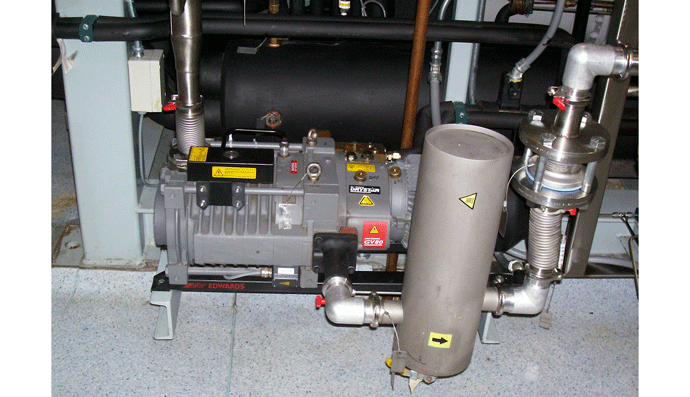
Dry pumps (Fig. 1) are being increasing popular as an alternative to oil sealed rotary vane pumps for many medium and high vacuum applications (e.g., in low-pressure vacuum carburizing where fine granular soot is carried from the process into the pump). Designers and users of vacuum furnaces must have a good understanding of how claw and screw pumps operate. This includes the principles of operation, pump design, sealing, operating characteristics, features, purging, and ancillary devices.
 |
|
| Figure 1 | Typical dry pump installation |
Claw Pumps
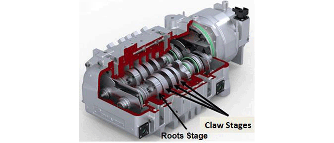
Although commonly used in series with a Roots style booster pump (Fig. 2), a claw pump can be used alone when high vacuum is not required and/or slower pumpdown rates are acceptable. Two and three-stage claw pump designs are typical, which utilize multiple claw rotors in series. Multiple-stage claw pumps reach a vacuum level of 1 x 10⁻¹ Torr (1.4 x 10⁻³ mbar) and pumping speeds up to 425 m3/h (250 ft3/min) while exhausting to atmospheric pressure. This can be increased to 0.7 x 10⁻³ Torr (1 x 10⁻³ mbar) and a speed of 800 m3/h (470 ft3/min) when used in combination with a Roots blower.
 |
|
| Figure 2 | Cutaway view of three-stage claw pump (with Roots booster) (courtesy of Edwards Vacuum) |
Principle of Operation
Of the various vacuum pump technologies, claw pumps are considered dry, positive displacement pumps. Dry, because the gas being transferred is not exposed to oil or water used in the pump, whereas wet pumps (e.g., liquid ring pumps) use oil, water or other fluids as a lubricant and to help provide a seal. Here, positive displacement refers to the fact that the pump works by mechanically trapping a volume of gas and moving it through the pump, creating low pressure on the inlet side.
Pump Design
The claw pump utilizes the Northey compressor mechanism. Two rotary lobes, which in cross-section look like claws, rotate in opposite directions within a stator housing (Fig. 3). They mesh along their length without touching. The claw rotors have a carefully engineered profile so that as they counter-rotate, separate expansion and compression chambers are created. Two complete rotations are required to pass through the inlet, compression, and discharge cycle. The rotation is synchronized through the use of a precision gear drive arrangement, with each claw rotor mounted to a separate shaft. In multiple rotor designs, several sets of rotors are mounted to two parallel drive shafts.
 |
|
| Figure 3 | Cross-sectional view of a dry claw pump2 |
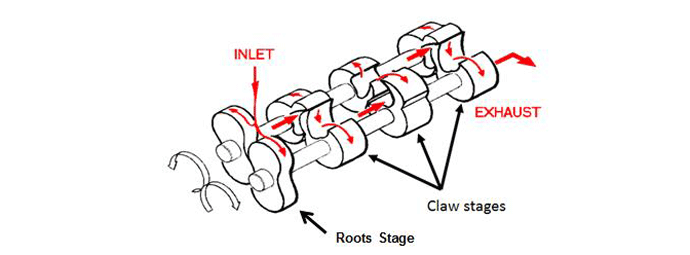
On the first rotation, the gas enters through an inlet port and fills the void between the first claw and the stator. On the next rotation, the trapped gas is conveyed to the second claw, where it is compressed and discharged when the discharge port opens. From there it exits the first stage in an axial direction and enters the second stage. As the claws continue to rotate, the gas moves axially from one stage to the next (Fig. 4). This creates a progressively higher pressure on the outlet side, and a lower pressure on the inlet side of the pump. A non-return valve is incorporated into the inlet flange to prevent air from flowing back into the vacuum chamber when the pump is turned off. The claw pump design is inherently noisy, and a silencer is required on the outlet side to reduce the sound level.
 |
|
| Figure 4 | Orientation of claws in a three-stage claw pump with Roots booster (courtesy of Edwards Vacuum) |
Pump Seal
Although not touching, there are only a few tenths of a millimeter of clearance between the meshing claws, as well as between the claws and the housing. This tight clearance, along with the viscosity of the gas and the kinetic motion of the claws rotating at high speeds, causes resistance to the backflow of gas by dragging the gas along with the claws, creating a non-contact, dry seal. The ultimate achievable vacuum is limited by gas backflow across these dry sealing surfaces.
In order to visualize the function of a claw pump, a live video animation is helpful (c.f., Reference 2).
Operating Characteristics of Dry Claw Pumps
In all dry pumps, contamination of the pumped gas is avoided. A claw pump is approximately 30% more efficient than a comparable rotary vane pump and uses less energy. However, because there is no oil present, claw pumps run hot, and discharge temperatures can reach over 260°C (500°F). This serves as an advantage in that it helps reduce condensation of pumped vapors, and related contamination. The higher operating temperature also enhances the pump’s ability to accept high temperature gases that would otherwise condense at lower operating temperatures. The claw pump also has favorable water vapor pumping characteristics for the same reason. On the other hand, this higher operating temperature may require continuous purging of the pump bearings and seals to prevent heat related premature failure.
The gearbox is sealed from the outside with shaft seals and O-rings, and the compressor chamber with piston rings. Between the two there is an atmospherically ventilated area that is purged with air or a special sealing gas. Purging is also used to provide protection of the seals and bearings against particulates or aggressive (corrosive) process gases.
Another feature found on claw pumps to prevent particulate buildup are scrapers. These are small elevated protrusions on the outside of the rotors where they are closest to the housing. The clearance between the scraper and housing is even smaller than the rotor and housing, and this causes the scraper to mechanically remove any particulates from the housing.
The claw rotors are often coated with polytetrafluoroethylene (PFA) or other Teflon® type material. The coating is extremely thin and allows for tighter clearances to produce a better ultimate pressure and higher efficiency of the pump. The coating also helps reduce corrosion. Over time, the spray-on coating will wear (affecting performance) and need to be reapplied.
Due to their high operating temperatures, claw pumps have the potential for auto-ignition when flammable gases are present. In addition, since they run hot, polymerization of process vapors can build up on the close running components, creating additional maintenance. In these situations, cool running claw pumps are preferred.
Claw Pump Designs Operating at Lower Temperatures
In situations where moisture or other vapors are present in the pumped gas, a claw pump running at reduced operating temperature may be desired. In these designs, the shape of the claw is such that it does not compress the gas during pumping, but merely transfers it. Since there is no compression, less heat is generated. In addition, these claw pumps use a gas heat exchanger on the discharge to provide cooling after the gas leaves the pump. The heat exchanger, which also serves as a condenser, is located at the pump outlet. It cools the discharge gas to an acceptable temperature, and also makes available cooled gas for injection. With gas injection, some of the cooled discharge gas is injected after the inlet port is isolated and the pumping chamber is at its maximum volume. Hot and cool gases mix and compress, increasing density (i.e, shrinking the volume). The discharge port is then opened and the compressed gas is pumped out. Because the heat exchanger serves as a condenser, it can be used for solvent recovery. Since it operates at atmospheric pressure, this is accomplished by simply draining the condensed liquids. No barometric leg or control system is required.
Claw pumps of this design also allow pumping of explosive and temperature sensitive gases. A two-stage cool running claw pump is the only dry pump that does not use mechanical compression to achieve vacuum. Because of this unique design, it can be started completely flooded with liquid. This provides a distinct advantage over other types of dry pumps. If the pump is starting to accumulate product buildup during operation, then it can be stopped and filled with a solvent to dissolve the buildup. The pump can then be started while flooded, pumping out the liquids. This also reduces downtime, as the pump would otherwise need to be taken apart and cleaned.
Purging
When processing corrosive gases, it is advisable to purge the claw pump with air prior to shutting it down. To purge the pump, the process inlet valve closes and a fresh air valve opens at the inlet. The pump runs for a prescribed time, 60 minutes for example, to remove residual process gas and condensates. Purging can be done manually or automatically. In manual purge mode the operator must start the purge cycle. In automatic purge mode, the pump will begin the purge cycle after the vacuum process is complete, prior to shutting down. In some pumps a 3-position switch is provided to select automatic purge, manual purge, or purge off modes.
Inlet Filter
A filter is provided on the inlet side of the pump to catch particulates. Varying types of filters are available and it is important to select a filter mesh fine enough to prevent pump contamination while not causing premature plugging of the filter. The filters must be periodically cleaned (with compressed air from the inside out) or replaced. Filter life is in the range of six months. Reduced pump performance is a good indicator that the filter should be changed before damage can occur.
References
- Herring, Daniel H., Vacuum Heat Treatment, BNP Media, 2012.
- Precision Plus Vacuum Parts, PPlusVac (youtube) video
