If you are a homeowner with a garden and a lawn, watering and mowing are regular tasks that need to be carried out. When you are watering your flower bed or vegetable patch at home you turn on the hose tap and see the water coming from the spray nozzle. You can then direct the water to the places where it is needed. Similarly, when mowing your lawn you can see what area you have already cut and can direct the mower to cut the next area of long grass. These tasks are made easier because you can see what you are doing. Trying to water or mow with your eyes covered would be much more difficult.
When you are evacuating a vacuum system, one of the biggest problems is that you can’t see what you are evacuating. Gas molecules are so small that you cannot see them. So how do you know when they have been moved out of the system and how do you know the best way to move enough of them to allow you to complete your particular process?
In this article we will try to understand what gas molecules are and how they behave at different pressures in a vacuum system. If you have a mental picture of the molecules using your imagination, it can possibly help you to understand how your vacuum system works and solve problems with its operation if something goes wrong.
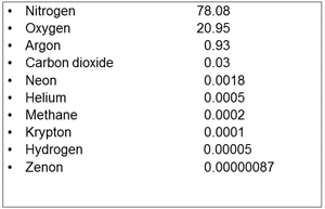 |
| Fig. 1 Composition of Dry Air by % |
Gases in Air at Atmospheric Pressure.
Let us “look” at air and “see” what it is made of. The most important constituent of air is oxygen – we need oxygen to breathe – without oxygen this conversation would not be happening. What are the other gases and how much of each gas is there? Fig. 1 shows the major gases present in air and the percentage of each that makes up a typical sample of air. The numbers do not add up to 100% as there are a few other trace gases that have not been included. Nitrogen and Oxygen make up about 99% of air, with Argon a distant third at less than 1%. The other gases listed and unlisted have very small volumes.
What isn’t included in Fig. 1 is Water Vapor. Humidity, water vapor in air, varies due to the local weather conditions. From various sources I checked it can range from 0.25% up to about 5% and may be on average just less than 1.6%. If a percentage of water vapor is included with the dry gases, the percentage volumes shown for the dry gases would be reduced slightly.
Knowing the gases in air is important in the vacuum industry because the main reason for creating a vacuum is to eliminate reactive gases from the vacuum chamber to allow the specific process to work correctly. The main reactive gases in air are oxygen and water vapor. The presence of oxygen in a vacuum system, especially if a hot process such as heat treating, can promote oxidation. Water vapor can break down into hydrogen and oxygen, but mainly causes problems in a vacuum system because it adsorbs onto the interior surfaces of the system and is difficult to pump away. For the same reason, leaks into a vacuum system should be eliminated because any oxygen and water vapor entering through a leak can allow unwanted reactions to occur which may affect the product being processed. A good example of that is discoloration of heat treated metal (oxidation) due to too much oxygen being present.
Gases in a Chamber under Vacuum
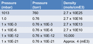 |
| Fig. 2 Gas Density at various pressures |
When the vacuum chamber has been loaded and the pump down process starts, the vacuum pumps will evacuate the chamber to the low pressure needed for a specific process. The dry gases such as nitrogen, oxygen, argon and most of the trace gases will be pumped away quite easily and the pressure in the system will drop. Even the smaller lighter molecules such as hydrogen and helium will be evacuated quite easily when an oil diffusion pump is the secondary vacuum pump. The vapor pressure of water at room temperature is about 18 torr. Once the chamber pressure is close to and below that pressure water vapor will start to evolve from the chamber walls and every surface inside the chamber including the work holders, insulation and the product itself.
If the process is hot, water vapor will start to “desorb” at a higher pressure. The heat adds extra energy to the layers of water vapor molecules on every interior surface and the additional energy will cause them to release off the surface and be pumped away. Materials such as fire brick and insulation that are porous and have very large surface areas and oxidized metal surfaces (rusty) tend to hold the water vapor more than a smooth clean metal surface will. For some processes a “soak time” is part of the evacuation cycle to allow molecules of water vapor to slowly desorb from porous surfaces and small bore piping.
Size and Density of Gas Molecules
Pressure is caused by molecular collisions with the wall of a chamber, or on a surface. Gas molecules are extremely small and typically move in straight lines until they collide with each other or with a surface. When a collision occurs between molecules they will move off in whatever direction that collision causes. When a molecule of gas hits a surface it will reside there for a small fraction of a second and then release and move away, but in a completely random direction. Most visual demonstrations and animations of molecular movement that I have seen show the molecules “bouncing” off a surface at the opposite angle to that which they hit the surface, like a tennis ball for example. This appears to be a limitation of the software. The fact that the molecules actually release off a surface in random directions makes low pressure vacuum pumping very difficult. (More on that later.)
Gas molecules are extremely small. For example, a hydrogen atom has a size of 0.1 nanometers (nm), and 1 nm is a billionth of 1 meter. That is also difficult to visualize. If we know that an average human hair is 100,000 nm thick, does that help?
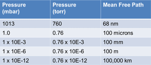 |
| Fig. 3 Mean Free Path |
The density of gas molecules also varies with the pressure. If we take a 1 cm3 sample of gas – close to the size of a sugar cube – at atmospheric pressure (14.7 psia) there are about 27 million, million, million molecules of gas in it. That number can be rewritten as 2.7 x 10¹⁹ molecules, all moving at high speed and frequently colliding with each other. These molecules however, are so small that there is still a lot of space between each of them. Can you imagine that?
Fig. 2 is a table that shows gas density at various pressures for comparison. A pressure of 1 x 10⁻³ mbar is about the ultimate of a two-stage oil sealed vacuum pump. The pressure of 1 x 10⁻⁶ mbar represents the approximate vacuum an oil diffusion pump creates. 1 x 10-12 mbar is about the pressure on the surface of the moon. Lastly 1 x 10-21 mbar approximates the pressure in outer space where there may only be 4 molecules of gas in each cubic meter of space.
Mean Free Path
Mean Free Path is the average distance between collisions of molecules. It will vary with pressure. Gas molecules move in random directions at any pressure and collide with each other and also with any surface if in a chamber. At atmospheric pressure the average distance between molecular collisions is 68 nm (nanometers). A nanometer is one billionth of a meter, not easy to visualize. If we compare it to the diameter of a human hair, a human hair is 100,000 nm. Another comparison would be the line width of some of the latest “electronic wires” in a semiconductor device or computer chip. Some of these tiny circuits have line widths of only 22 nm.
As the pressure drops in a vacuum system, the density of the gas molecules is reduced and the mean free path increases. The table in Fig. 3 shows how the mean free path becomes very long at low pressures. At 0.76 x 10⁻⁶ torr the mean free path is 100 meters or about 300 feet. That indicates that in a 10 feet diameter vacuum chamber under high vacuum conditions the gas molecules are much more likely to strike a chamber surface several times before they collide with another gas molecule.
Gas Flow in Vacuum Systems
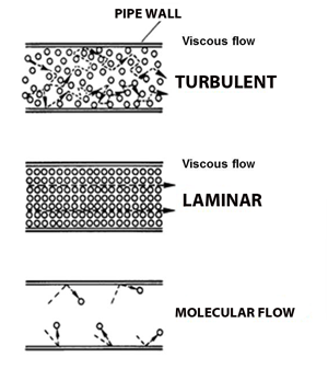 |
| Fig. 4 Flow Regimes |
Kinetic gas theory explains that molecules of gas at normal conditions act independently in that they move at high speed and colliding frequently with other molecules or if in a chamber or pipe the surfaces of that constriction. It also goes on to say that the gas, as a whole, will move as a mass of gas: i.e. it will flow along a pipeline towards a lower pressure in an attempt to equalize that pressure.
That said, gas in a vacuum system at normal conditions, between atmospheric pressure and somewhere slightly below 1 torr, is dense enough that it will flow towards the lower pressure – the mechanical pump inlet. This applies to chambers being pumped directly by a mechanical vacuum pump that has an ultimate vacuum lower than about 100 microns (1 x 10⁻¹ torr). If the pressure is much below that value the flow characteristics change and another set of circumstances come into effect.
There are three types of gas flow considered when working with vacuum systems: viscous (or continuum) flow, transitional flow and molecular flow. Fig. 4
Viscous flow occurs at the higher pressures, as just mentioned, when the gas is dense enough to flow towards a lower pressure. In this type of gas flow the mean free path of the gas molecules is less than the diameter of the pipeline or chamber or even section of the chamber where the molecules are flowing. As long as the gas molecules are colliding with each other more frequently than with the surfaces they are close to, they are said to be in viscous flow conditions.
In this flow regime, viscous flow, the gas molecules will be colliding with each other and with the inside surface of the piping and also flowing as a mass towards the inlet of the primary mechanical pump.
Mechanical pumps, wet (oil sealed) or dry can evacuate gas molecules that are at a high enough pressure that they flow under viscous flow conditions. Viscous flow also varies depending on the pressure and conditions, Fig. 4, at higher pressure it behaves in a turbulent condition and as the pressure drops to somewhere below about a 100 torr it appears to settle and flow in a more laminar condition.
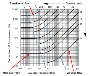
When the mean free path of the gas molecules becomes longer than the diameter of the piping, or component, the gas flow changes into molecular flow and does not actually flow any more. At this point the molecules of gas collide with the inner surfaces of the piping or chamber more often than they collide with another gas molecule. When they do touch the walls they reside for a very short time and then release in a completely random direction. (They are unpredictable and do not “flow”, something akin to herding cats.) Calling it molecular flow is a misnomer; perhaps “molecular random movement” would be more descriptive. This generally occurs below about 1 x 10⁻¹ torr depending on the diameter of the piping. To pump gas molecules when they in molecular flow a secondary vacuum pump is required, either an oil diffusion pump or a turbomolecular pump for most vacuum furnace systems. The only way to move the gas molecules when they are in molecular flow conditions, probably at a pressure of 1 x 10⁻² torr or below, is to have a vacuum pump with a large inlet that allows as many of the randomly moving gas molecules to enter the pumps as practical for the application. Once the molecule of gas has entered the pump inlet the pump mechanism has to move it down into the pump interior and not allow it to escape back out of the pump inlet. In molecular flow conditions, pumping speed depends entirely on the size of the secondary vacuum pump inlet. How the secondary vacuum pumps move the molecules is another discussion.
 |
| Fig. 5 Conductance in pipes |
As the pressure in the vacuum pump drops and the gas flow reaches the lower end of viscous flow regime, there is an area where the flow is changing from viscous flow to molecular flow, it does not occur instantly. That area is called the transitional flow area and can be seen on Fig. 5. It is at this point in the process where the rough pumping, by the mechanical vacuum pump is changed over to fine pumping by the secondary vacuum pump. This changeover point varies with the size of the piping and other design factors of the specific system. It can be seen on Fig. 5 that the transitional flow pressure range is lower as the pipe diameter increases. From about 1 to around 3 x 10⁻² torr for a small 5 mm bore pipe, down to the 1 x 10⁻² to 1 x 10⁻³ torr area for a 250 mm (10 inch) diameter pipe.
At this point the subject of gas molecules and gas flow in a vacuum system has been introduced, I hope, in easy enough language that it can be understood. As stated at the beginning, understanding something that you cannot see can be difficult. The numbers on the left side of Fig. 5 show values of Conductance for 1-meter lengths of piping.
In the next article we will return to this picture, learn a bit more about conductance and also the term throughput.
References
Figures 1, 4 and 5 are from the 3rd edition of the textbook “Modern Vacuum Practice” by Nigel Harris. The tables shown in Figures 2 and 3 have been developed from Wikipedia material.
Copyright Howard Tring, Tring Enterprises LLC Vacuum & Low-Pressure Consulting.
