We continue our discussion about vertical vacuum furnaces by focusing on designs utilizing an oil quench tank.
Vertical Oil Quench Vacuum Furnaces
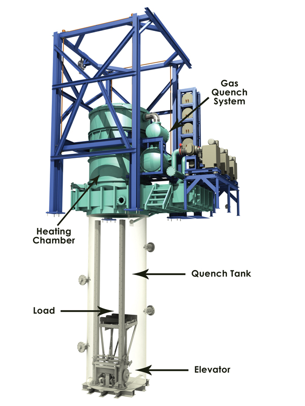
A typical vertical oil quench vacuum furnace (Table 1) either utilizes a heating chamber mounted atop a movable gantry so that loads can be transferred in and out of the furnace and oil quenched in a separate oil tank or designs in which the main furnace chamber is stationary and separated by an isolation valve from a loading vestibule/oil quench tank.

* Workload dimensions are 1473 mm wide x 1220 mm long x 2895 mm high (58” wide x 48” long x 114” high)
Furnace Operation
As an example of the former arrangement, during loading, the gantry moves the heating chamber aside and a new load is placed onto the quench elevator. Prior to this, the quench oil was transferred to a reservoir tank so as to avoid contact with the load prior to entry into the vacuum chamber. The elevator lowers the load into the empty quench tank, and the heating chamber moves back into position over the quench tank, then lowers and seals to the quench-tank flange. Next, the vacuum seal door and hearth doors within the heating chamber open, and the elevator raises the load into the heating chamber. As the elevator withdraws into the quench tank, the hearth doors close to support the load and the seal door closes to isolate the heating chamber. After the loading sequence is complete, the quench oil is pumped back into the quench tank from the reservoir tank.
After pumpdown, ramping and stabilizing at the hardening temperature, the chamber is backfilled with nitrogen gas to equalize the pressure between the chamber and the oil quench tank. The furnace doors then open, and the elevator raises to support the load and then descends quickly (within 10 seconds) into the quench tank to complete the process.
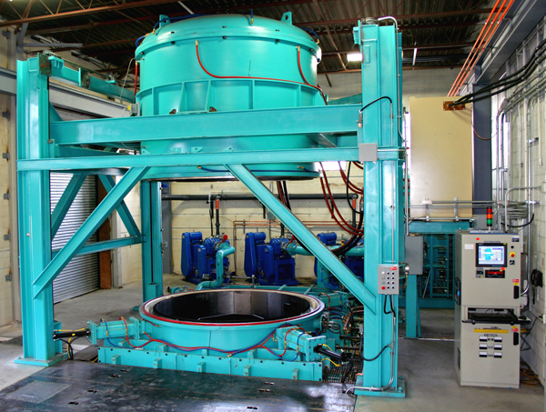
Another example is a vertical oil quench vacuum furnace (Fig. 1) capable of running a workload of 1,600 kg (3,500 pounds) in a 1.8 m (72 inches) diameter by 1.9 m (76 inches) high chamber. Parts are loaded vertically onto a support fixture. The furnace bell is raised into the up position, exposing the hearth table. The seal door separating the quench tank from the hot zone is closed. After the load is placed on the hearth table, the loader is retracted out of the furnace and the bell is lowered.

The furnace is pumped down and processing commences. During processing, the furnace chamber is evacuated to a pressure of approximately 10-2 mbar (7.5 x 10⁻³ torr). The oil quench tank is also evacuated to a pressure of approximately 400 mbar (300 torr). When chamber evacuation reaches a preset pressure, heating of the load starts until the recommended austenitizing temperature (Table 2) is achieved.
Heating ramp rates are selected to minimize thermal gradients within the load without creating excessive cycle times. Control of the ramp rate during heating is an important factor in relieving stresses that may have been created during machining of the components being heat treated. During heating, the load is also held at an intermediate temperature around 620°C (1150°F) for a short period of time to further improve temperature uniformity. Maintaining temperature uniformity throughout the cycle is essential to prevent the buildup of thermal stresses and to ensure that all sections of the load undergo the microstructural transformations needed to achieve the desired mechanical properties.
After the load is soaked for a sufficient period of time at the austenitizing temperature, the oil quenching process can begin. The first step in this process is the backfilling of the furnace chamber (with nitrogen gas) to 400 mbar (300 torr) or just below atmospheric pressure to equalize to the pressure in the oil quench tank between the furnace and the oil quench.
Next, the vacuum seal door is opened and the quench elevator is raised to a point where it again supports the weight of the load. The load bars are then retracted, and the elevator and load rapidly descend (within 10 seconds) into the quench tank. After the load is lowered into the quench tank, power to the heating elements is shut off and the seal door is closed. The quench blower is then activated to cool the heating chamber to ambient temperature. The quench tank contains 35,000 liters (9,300 gallons) of quench oil. Electric heaters and coolers regulate oil temperature. Careful monitoring of quench-oil conditions is an important factor in part distortion control.
At the end of the cycle, the furnace is backfilled with nitrogen to atmospheric pressure and the bell is raised to the up position. The seal door opens up, and the elevator raises the load out of the oil (at slow speed) to the up position. The load bars extend, and the elevator lowers the hearth table and load onto the load bars. The elevator then lowers to standby position just below the seal door. The seal door closes, and the loader moves in to unload the parts from hearth table.
Managing Distortion
Several techniques can be used to control distortion during heat treating. Normalizing of the material prior to heat treatment is one such technique. For components that become highly stressed from manufacturing operations prior to the hardening treatment such as forging and/or machining, a separate stress relief cycle can be used. However, in most cases, these residual stresses can be relieved during the hardening cycle by slowing the heating rate and introducing holds at one or more preheat temperatures. The thermal shock induced by quenching hot steel in oil almost always causes some degree of dimensional distortion. This can be reduced by minimizing the temperature differential between the final hardening temperature and the temperature of the quench oil bath.
The precise control of surface chemistry that allows leaving minimal or no machining stock on the component prior to heat treating is a major advantage of these furnaces. The challenge in vacuum hardening then becomes counteracting any dimensional change (thermal, phase transformational or quenching) so as to yield a heat treated component within the required dimensional tolerances.
Fixturing is an important part of managing distortion. For example, long components are typically hung from the fixturing to take advantage of the force of gravity as a stabilizing influence. Components incorporating major differences in section thicknesses are especially prone to distortion due to different rates of heating and cooling between thin and thick sections. For these components, extra stock allowance or heat sinks attached to the thinner sections are sometimes used to provide a better thermal balance.
Oil composition, temperature, and agitation can also influence distortion (Fig. 2). Some oil compositions are designed to achieve higher quenching speeds than others. High-speed oils are preferred for hardening very thick sections and achieving maximum strength in steels having lower hardenability. However, they can also cause greater levels of distortion in thin sections or in steels having high hardenability. Cooler, more highly agitated oil also creates more thermal shock. Oil temperature and agitation are carefully regulated in specific hardening applications by using controls device built into the quench tank.

Interrupted (Ausby) Quenching
Interrupted quenching techniques such as Ausbay quenching has been used to reduce distortion in certain grades of high strength steel. Ausbay quenching involves rapidly cooling the steel from the austenitizing temperature to an intermediate temperature above that where martensitic transformation begins. The intermediate temperature range corresponds to a wide austenitic “bay” region on the isothermal transformation diagrams for the steel. Cooling from the austenitizing temperature to the Ausbay region must be sufficiently fast to avoid the nose of the transformation curve and corresponding formation of undesirable products of austenitic transformation. This is accomplished by activating the gas quench system.
With heating element power off, the gas quenching process continues until the temperature of the load reaches about 540°C (1000°F). The rate of cooling during the gas quenching stage must be carefully controlled so that it is fast enough to avoid any decomposition of austenite but not so fast that the load is cooled below the required Ausbay temperature. The flow of gas circulated through the load during the quenching stage is regulated by a damping valve in the inlet of the manifold. Normally open for maximum cooling rate, this valve starts to close as the Ausbay temperature is approached. Power to the heating elements is also gradually returned. Both quench gas flow and heating element power is automatically regulated through the use of microprocessors in the furnace control system. Input from thermocouples in the heating chamber provides the microprocessors with real-time data so cooling rate corrections are made instantaneously.
When the gas quench system is deactivated, sufficient power is applied to the heating elements to maintain the load at the Ausbay temperature, where it is held at the soaking temperature until a uniform temperature is achieved throughout the workload. Many high strength steels can be held in the Ausbay temperature range for several hours without any austenitic transformation. After a sufficient soak, the load is quenched in oil using the same sequence of events as described previously. By interrupting the cooling process, the ausbay quenching technique reduces thermal shock and the stresses it creates. This results in corresponding improvements in dimensional stability of the heat treated component.
This technique is used on several critical landing gear components fabricated of 300M steel. Comprehensive analyses show that Ausbay quenching reduces quench-related distortion in these components by more than 50% compared with direct oil quenching.
Application Example
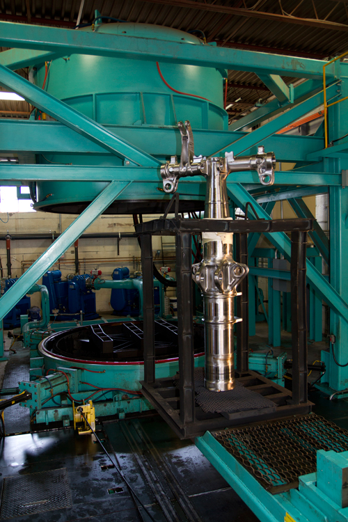
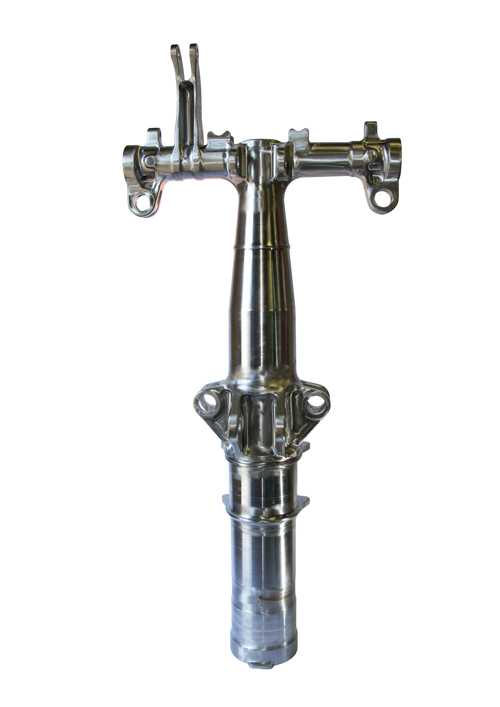
Vacuum oil quenching (Fig. 3) offers the economic and environmental benefits for processing many critical-performance components such a landing gear bogie beams (Fig. 4). Since vacuum furnaces are inherently leak tight, control of surface chemistry is assured, and problems with decarburization and high-temperature oxidation are avoided. Vacuum processing also allows producers of aircraft landing gear to finish machine critical surfaces on these components prior to heat treating. This, in turn, reduces final machining costs when the part is in the hardened condition. Further, quench-related distortion is minimized through load transfer to the quench tank via a high-speed elevator. Warm or hot straightening can be used when necessary to compensate for any dimensional changes.


Vacuum heat treatment (Table 2) followed by oil quenching and double tempering produces a microstructure with high strength and excellent toughness, ideal for applications involving heavy loading and fatigue. During hardening, internal stresses created from the thermal shock of direct oil quenching almost always cause some degree of distortion in these components. A final machining allowance is often left on critical dimensional features to compensate for distortion. Due to the difficulty of machining these alloys in the hardened condition, however, machining allowances must be minimized. In the current environment of cost and lead-time pressures, reducing distortion during thermal processing has become a primary objective for heat treaters of landing-gear components.

Notes: 1. Tempering temperature depends on final properties (except for 300M)
Conclusion
The flexibility of having designs that perform gas quenching (Part One) or oil quenching (Part Two) ensures that the focus on the producing proper mechanical and metallurgical properties in a controlled vacuum environment with minimal part distortion. Material, part geometry, specification compliance and other requirements play a role in helping to select the best equipment for the job.
References
1. MacKenzie, Scott, Heat Treatment of Landing Gear, Heat Treating Progress, May/June 2008.
2. Vanderpol, Paul and Carmine Filice, Daniel H. Herring, “Landing-Gear Heat Treatment”, Industrial Heating, November 2011.
3. Vac-Aero International Press Releases:
a. Vac Aero to Add Fourth Large Vacuum Oil Quench Furnace
b. Vac Aero Leads the Industry in the Vacuum Oil Quenching of Landing Gears
c. VAC AERO Operates three of the Largest Oil Quench Furnaces
d. Integral Oil Quench Vacuum Furnaces
e. Vacuum Hardening High-Strength Steels: Oil Vs. Gas Quenching
