Vacaero

Manufacturers of heat treating and brazing vacuum furnaces and controls, complete hot zone and vacuum furnace retrofits, thermal spray coatings, plasma, HVOF and paint coating services.

VAC AERO Service Experience Trust
Canada FrançaisAccessibility |
  • Home
  • Company
  • Vacuum Furnaces
  • Thermal Processing
  • Coatings
  • Service & Support
  • Resources
  • Contact Us
  • Request for Quote

Cold Traps

September 1, 2017 by VAC AERO International

Cold Traps

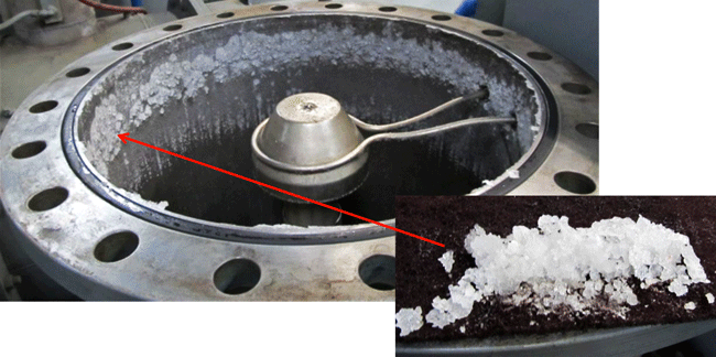
In vacuum applications, cold traps are added to vacuum pumping systems either to remove unwanted contaminants (e.g. water, solvents, acidic or alkaline compounds) from the gas stream or to prevent pump backstreaming. These conditions can cause a loss of efficiency or damage when introduced into or emanating from the vacuum pumping system. In simplest terms, cold traps work by sublimating a gas molecule, that is, by transforming the molecule directly from the gas phase to the solid (crystalline) phase thus bypassing the liquid phase. The gas crystallizes out on a cold metal surface often appearing as “frost” on the trap.

Cold traps should be chosen that are large enough and cold enough to collect the condensable vapors in a vacuum system. Cold traps and cold caps refer to the application of cooled surfaces or baffles to prevent oil vapors from backstreaming (i.e. oil migration from the pumps into the chamber). In such cases, a baffle or a section of pipe containing a number of cooled vanes will be attached to the inlet of an existing pumping system. By cooling the baffle, either with a cryogenic liquid such as nitrogen, or by use of an electrically driven Peltier element (a thermoelectric heat pump device in which one side is cooled while the opposite side heats up when a voltage is placed across the device and which transfers heat from one side of the device to the other), oil vapor molecules that strike the baffle vanes will condense and thus be removed from the pumped cavity.

Vacuum Technology at CERN

August 8, 2017 by VAC AERO International

Vacuum Technology at CERN

CERN (Conseil Européen pour la Recherche Nucléaire) is located in a northwest suburb of Geneva, Switzerland and is the world’s leading center for collaboration on nuclear research. One of its many activities involves the study of  particle physics.

Particle physics is conducted in machines known as particle accelerators (aka particle colliders). These use electromagnetic fields to accelerate particles to high speeds and focus them into a fine beam. The world’s largest and most powerful particle accelerator, the Large Hadron Collider (LHC) began operation at CERN in 2008. The LHC (Figure 1) is a 27 kilometer (16.8 mile) ring of superconducting magnets held at temperatures colder than outer space. Within this machine subatomic particles smash together at near light speed in an ultrahigh vacuum. It has allowed scientists unique insights into the fundamental building blocks of matter

Considerations in Vacuum Vessel Design

August 6, 2017 by VAC AERO International

Considerations in Vacuum Vessel Design

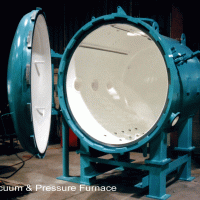
Vacuum furnaces come in all shapes and sizes but common to each is that they require some type of vacuum vessel (Fig. 1). Most vacuum vessels in the heat treating industry are cylindrical in shape and either horizontal or vertical in orientation (Fig. Nos. 2 – 3). In general, vacuum vessel designs are made as small as possible so long as they don’t hamper the process being run in the vessel. There are several obvious reasons for this including the cost of the vessel itself as well as the vacuum hardware involved. In addition pumping systems become larger and operating costs tend to be higher (e.g. more gas is required for quenching).

Designs for vacuum vessels involve two distinct aspects; one structural and one related to the process application. The basic structural design falls in the realm of mechanical engineering following established industry guidelines, an example of which is the ASME Boiler and Pressure Vessel Code, Section 8 Division 1 (Rules for Construction of Pressure Vessels) for vacuum furnaces utilizing high-pressure gas quenching (above 14.7 psig). The design must take into account both the external and internal forces acting on the vessel to prevent buckling (i.e. structural instability) and deal with overpressure issues, both major concerns from a strength of materials standpoint.

Space Simulation Chambers – Part 2

July 11, 2017 by VAC AERO International

Space Simulation Chambers – Part 2

The demands on space simulation chambers from the extremes of temperature and vacuum were discussed in Part One along with the development of space simulation chambers (aka space simulators) for testing of components used on vehicles for space travel such as sensors, landers and ion thrusters (Fig. 1) under the same conditions they will encounter during deployment in space. We continue this discussion by exploring the vacuum systems used to make these chambers function properly.

There is a wide range of commercially available space chambers, from small 460 mm diameter x 610 mm long (18” diameter x 24” long) units, to field-erected systems large enough to enclose a satellite, rocket section or space telescope. These large units can be 15.2 m (50 ft.) or more in diameter.

Finding and Fixing Vacuum Leaks

July 7, 2017 by VAC AERO International

Finding and Fixing Vacuum Leaks

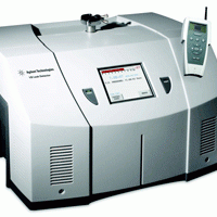
Finding leaks in vacuum furnaces is a task that few of us cherish but all of us know is important and necessary. Leaks are a problem experienced by almost every vacuum user. Leaks can occur suddenly or develop slowly over time but in either case, they are damaging both to product quality and to furnace internal components. In extreme cases, the problem is obvious: the furnace will not pump down and/or the hot zone (or heating elements) shows obvious signs of attack. Tiny leaks, however, are more common often going undetected because of the pumping systems ability to overcome them. However, even small leaks can cause continuous and sometimes catastrophic damage. Thus, routine leak checking and leak repair should be a part of any good vacuum furnace maintenance program.

Like any job, leak detection can be made easier by having the right tools, looking in the right places, having patience and using a great deal of common sense. Leaks can be inherent in the materials of construction, created during the manufacturing process, be introduced during maintenance or repair, or occur over time due to corrosion, wear, fatigue or stress. The question is: “Can the system tolerate the leak?” In other words, can the process and equipment survive the consequences of the leak? The answer is almost always, “No.”

The most obvious place to look for a leak is in and around the last place that was repaired or serviced. Begin by asking the question, “What was the last area worked on or modified? ” (e.g. thermocouples, power feedthroughs, door “O” rings, etc.). It is incredible how many leaks are found and corrected by simply asking questions before one begins leak detection in earnest.


Preventive Maintenance Extends Hot-Zone Life

June 13, 2017 by VAC AERO International

Preventive Maintenance Extends Hot-Zone Life

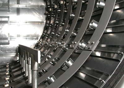
Stretching the service life of a hot zone-one of the most expensive consumables in a vacuum furnace-is of prime importance to the furnace owner. Proper care and maintenance can slow down hot-zone deterioration, which directly translates to cost savings. Hot-zone service life is directly related to the type of heat treating process used in a vacuum furnace and to the severe thermal stresses imposed by continuous vacuum-furnace cycles. Distortion and contamination are the main factors causing a breakdown of hot-zone components. Distortion is inevitable because thermal cycling is inherent to the process. However, periodic inspection and remediation of hot-zone components together with thorough component cleaning can extend service life.

Two main types of hot zone construction used in vacuum furnaces today are an all-metal zone and a carbon-felt zone. An all-metal zone consists of several layers of sheet metal, such as molybdenum, stainless steel, and tantalum, separated by channels. The choice of material depends on operating conditions. For example, a zone that will be subjected to an operating temperature of 2400°F (1315°C) could consist of two inner layers of molybdenum backed by three layers of stainless steel. A hot zone intended for use at temperatures to 2600°F (1430°C) generally is made entirely of molybdenum. Reflective heating is used in an all-metal zone; that is, radiation from heating elements is reflected off the inner layer of molybdenum back to the parts being treated. Heat is contained in the hot zone through the use of channels, which create gaps between each sheet metal layer. Each gap creates an area of insulation with each successive layer being cooler.

Space Simulation Chambers – Part 1

June 6, 2017 by VAC AERO International

Space Simulation Chambers – Part 1

Manufacturers of materials, components, and machines for spacecraft and satellites deployed in space must vigorously test them prior to putting them into service. For example, linear actuator mechanisms on satellites have failed to function properly (extend or retract) because of a loss of tolerance due to the conversion of retained austenite to martensite and subsequent growth of the part due to volume expansion. Had this test not been performed in a simulation chamber at -62ºC (-80ºF) here on Earth, a solar array or communications antenna would not have deployed when the satellite was in orbit and its mission would have been compromised.

In order to ensure thermal and vacuum readiness of these systems prior to lift off, they must be subjected to the extreme vacuum and temperature of space to ensure they can withstand and perform under these harsh conditions without failure. Space simulation (aka space test) chambers are used to perform this testing. The challenging conditions encountered in space and the development of the space simulation chamber are the focus of our discussion.

  • « Previous Page
  • 1
  • …
  • 4
  • 5
  • 6
  • 7
  • 8
  • …
  • 19
  • Next Page »
  • Vacuum Heat Treating: Education & Training
    • News & Announcements
  • Vacuum Technology with The Heat Treat Doctor
  • Vacuum Pump Technology: Education & Training
  • Metallography with George Vander Voort
  • Q’s and A’s
  • “What’s Hot!” Newsletter
  • Glossary Metallurgical Terms
Vertical vacuum furnace specifications
horizontal vacuum furnace specifications
Vacuum Furnaces
Vacuum Furnace Zone Rebuilds
Technical Articles and Resources

Specialists in Vacuum Furnace Technology - High Quality Vacuum Furnace Manufacturer

COMPANY

  • VAC AERO Products & Services
  • Company History
  • Certificates & Approvals
  • Employment Opportunities
  • Values & Commitment
  • Corporate Sponsorship
  • Corporate Brochure
  • Terms & Conditions of Use
  • Privacy Policy

FURNACE MANUFACTURING

  • Horizontal Furnace Specs
  • Vertical Furnace Specs
  • Hot Zones
  • Control Systems
  • Custom Vacuum Furnaces
  • Quality Control
  • Service & Support
  • Furnace Request For Quote (RFQ) Form

THERMAL PROCESSING

  • Ontario – Plant 1
  • Ontario – Plant 2
  • Quebec – Thermal Processing Division
  • Specific Heat Treating & Brazing Approvals
  • Metallurgical Services Matrix

COATINGS

  • Quebec Coatings Division
  • HVOF Spray System
  • Specific Coating Approvals
  • Metallurgical Services Matrix

SERVICES & SUPPORT

  • Furnace Rebuilds & Upgrades
  • Hot Zone Rebuilds
  • Process Controls Upgrades
  • Ordering Parts
  • Field Service
  • Training Seminars

© Copyright 2016 VAC AERO - All rights reserved. Site Map Contact Terms and Conditions Privacy