Vacaero

Manufacturers of heat treating and brazing vacuum furnaces and controls, complete hot zone and vacuum furnace retrofits, thermal spray coatings, plasma, HVOF and paint coating services.

VAC AERO Service Experience Trust
Canada FrançaisAccessibility |
  • Home
  • Company
  • Vacuum Furnaces
  • Thermal Processing
  • Coatings
  • Service & Support
  • Resources
  • Contact Us
  • Request for Quote

Abradable Coatings used for Gas Path Seals in Turbine Engines

January 25, 2014 by VAC AERO International

Abradable Coatings used for Gas Path Seals in Turbine Engines

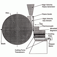
For maximum fuel efficiency, many gas turbine engine designs depend on sacrificial coatings to tighten internal clearances between moving parts. An extra gap of .005″ between the rotating blades and the engine casing can increase fuel consumption by as much as 0.5%. As fuel comprises more than half of direct operating costs, this waste can be significant. Engine efficiency largely depends on close clearance between blades and casing. Clearance can be affected by a number of engine operating variables, including casing expansion and contraction, loading due to maneuvering, thrust, gust, stall, vibration and manufacturing tolerances. An industrial turbine engine manufacturer (“OEM”) was experiencing unsatisfactory results with the ring segment coatings used to maintain rotor-shroud clearance. Because of poor abradability, the coatings cause excessive wear on the tips of the turbine blades. The OEM and VAC AERO agreed to work cooperatively to develop an improved abradable coating for these applications.

Materials normally used in sacrificial coatings for gas path seals include sintered metal-powder segments, sintered metal-fiber segments, metallic honeycomb (filled and unfilled), elastomers and thermally sprayed abradable coatings. Thermally sprayed coatings offer advantages over the other materials, including direct application, easy removal and repair, variety of coating materials and good performance. New abradable thermal spray coating materials have been proposed for performance in industrial turbine engines at operating temperatures up to 980°C.

An investigation of a variety of these new materials was under taken in order to quantify their performance during cyclic oxidation burner rig testing, hot corrosion burner rig testing and hot abradability rig testing as compared to existing abradable coating technology. Based on the results of these tests it was concluded that a significantly improved coating for abradable seals in industrial gas turbine engines was developed. This new coating can prevent excessive blade tip wear between 24,000-hour inspection intervals at operating temperatures up to 980°C. The successful coating consists of a specially heat treated MCrAIY bond coat, applied by HVOF, covered with a proprietary abradable top coat, applied by air plasma spray. By Jeff Pritchard, Scott Rush and A. Kiela

The Role of Lubricants in Vacuum Furnace Seals

January 17, 2014 by VAC AERO International

The Role of Lubricants in Vacuum Furnace Seals

Lubricants for vacuum service are a diverse family of highly formulated products. The types of lubricants for vacuum service fall into three general categories: (a) wet, organic or silicone-compound based oils and greases, (b) dry lubricants including PTFE (Teflon®) and metal dichalcogenide compounds (e.g. molybdenum disulfide, tungsten diselenide) and (c) metal on metal combinations.

The choice of lubricant depends on a number of considerations that are highly dependent on the specific end-use applications including; operating temperature and vapor pressure, the presence or absence of sliding or rolling motion, the presence or absence of reactive species (e.g. plasma), loading characteristics and frequency of usage. Lubricants are used in a vacuum system for three primary reasons: (1) in an “O” ring sealed system to help minimize externally applied forces on the ring material, (2) between moving surfaces to reduce the coefficient of friction, minimize wear and/or reduce/eliminate the formation of particular matter and (3) as anti-seizing agents where mating surfaces are likely to seize.

Simple Physics for the High Vacuum Processing Industry

January 14, 2014 by VAC AERO International

Simple Physics for the High Vacuum Processing Industry

States of Matter – All matter consists of atoms, and some atoms combine with others in a chemical reaction to form molecules. For example, water consists of two atoms of hydrogen combined with one atom of oxygen (H2O). Some gases such as argon (Ar), helium (He) and neon (Ne) are unlikely to combine with a similar or dissimilar atom, while others such as hydrogen, nitrogen, and oxygen and usually combine with an identical atom forming a molecule (H2, O2 and N2) and are called diatomic.

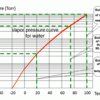
Matter is divided into three states: solid, liquid and gaseous. Some matter can exist in each of the three states, for example, water that can be ice (solid), water (liquid) and steam (vapor) depending on the surrounding pressure and temperature (Fig. 1). Another example is carbon dioxide that can also exist in all three states.

The Solid state (Not to be confused with “solid state” electronic components)

In a solid, the atoms are bound tightly together in fixed positions relative to each other by interatomic forces. Therefore a solid has a fixed volume at a specific pressure and temperature. Changes in temperature will change the energy in the atoms and cause tiny vibrations about their position but the bonds are relatively strong and most solids can withstand reasonable temperature changes without breaking down apart from small expansion or contraction if the temperature changes. Even though a solid appears “solid” there are very small spaces between individual molecules. Metal solids, which are ones most prevalent in the vacuum furnace and heat treating industry, all have a melting point and if enough heat is applied the solid will eventually change to a liquid. This liquid, if more heat is added will eventually evaporate and change to a vapor.

Pressure and Throughput Distribution in Vacuum Systems

November 12, 2013 by VAC AERO International

Pressure and Throughput Distribution in Vacuum Systems

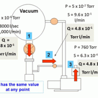
Last time the discussion was about throughput and conductance in vacuum systems. This time we will look at the pressure profile throughout the vacuum system in a slightly different way than it was shown last time. The first thought might be that once the vacuum system is under vacuum carrying out the process, the lowest pressure will be in the vacuum chamber and that the highest pressure will be at the primary pump exhaust which will be atmospheric pressure. As we see from Fig. 1, this is not quite correct.

Fig. 1 shows how the pressure changes through the system and actual values of P pressure and S speed are given in the table, Fig. 2. The pressures shown assume that the chamber has been evacuated (pumped down) to the process pressure needed and conditions are stable.

Conductance & Throughput in Vacuum Pipelines

October 10, 2013 by VAC AERO International

Conductance & Throughput in Vacuum Pipelines

Last month we discussed Gas Molecules and Gas Flow and at the end of the article mentioned the term Conductance. This time we will talk a bit more about conductance in vacuum system piping and why it has to be taken into consideration in the design of a typical vacuum furnace or similar vacuum system.

Firstly though, we will discuss Throughput. Have you ever wondered why vacuum pipes and connections are of several different sizes on any vacuum system? I would suggest that most users don’t really give it any thought. It is what it is. So let’s look at the sections of a vacuum system and again try to visualize those gas molecules, which are so tiny we can’t see them, and understand the conditions at different places in the system.

Gas Molecules and Gas Flow

September 11, 2013 by VAC AERO International

Gas Molecules and Gas Flow

If you are a homeowner with a garden and a lawn, watering and mowing are regular tasks that need to be carried out. When you are watering your flower bed or vegetable patch at home you turn on the hose tap and see the water coming from the spray nozzle. You can then direct the water to the places where it is needed. Similarly, when mowing your lawn you can see what area you have already cut and can direct the mower to cut the next area of long grass. These tasks are made easier because you can see what you are doing. Trying to water or mow with your eyes covered would be much more difficult.

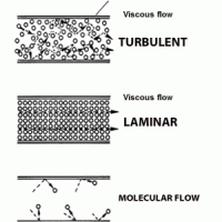
When you are evacuating a vacuum system, one of the biggest problems is that you can’t see what you are evacuating. Gas molecules are so small that you cannot see them. So how do you know when they have been moved out of the system and how do you know the best way to move enough of them to allow you to complete your particular process? In this article we will try to understand what gas molecules are and how they behave at different pressures in a vacuum system. If you have a mental picture of the molecules using your imagination, it can possibly help you to understand how your vacuum system works and solve problems with its operation if something goes wrong.

Shaft Seals for Rotating Shafts

August 13, 2013 by VAC AERO International

Shaft Seals for Rotating Shafts

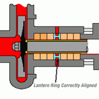
On any machine that has a rotating shaft there will be a shaft seal of one type or another. If the machine is a simple electric motor, for example, the seal may be used just to retain the lubricant in the bearings and to prevent dust and dirt from entering the bearing. This type of seal generally needs little or no maintenance for small motors from ¼ to perhaps 10 HP.

The shaft seals in any pump that the electric motor drives are ones that do need maintenance and replacement, whatever type of pump it is. If the pump moves liquids, such as a centrifugal water pump, it is important that the seal doesn’t leak although in some applications a small amount of leakage can be tolerated. If the liquid being pumped is hydraulic fluid, it may be at high pressure and the seal would be designed to withstand that pressure without failing.

  • « Previous Page
  • 1
  • …
  • 11
  • 12
  • 13
  • 14
  • 15
  • …
  • 19
  • Next Page »
  • Vacuum Heat Treating: Education & Training
    • News & Announcements
  • Vacuum Technology with The Heat Treat Doctor
  • Vacuum Pump Technology: Education & Training
  • Metallography with George Vander Voort
  • Q’s and A’s
  • “What’s Hot!” Newsletter
  • Glossary Metallurgical Terms
Vertical vacuum furnace specifications
horizontal vacuum furnace specifications
Vacuum Furnaces
Vacuum Furnace Zone Rebuilds
Technical Articles and Resources

Specialists in Vacuum Furnace Technology - High Quality Vacuum Furnace Manufacturer

COMPANY

  • VAC AERO Products & Services
  • Company History
  • Certificates & Approvals
  • Employment Opportunities
  • Values & Commitment
  • Corporate Sponsorship
  • Corporate Brochure
  • Terms & Conditions of Use
  • Privacy Policy

FURNACE MANUFACTURING

  • Horizontal Furnace Specs
  • Vertical Furnace Specs
  • Hot Zones
  • Control Systems
  • Custom Vacuum Furnaces
  • Quality Control
  • Service & Support
  • Furnace Request For Quote (RFQ) Form

THERMAL PROCESSING

  • Ontario – Plant 1
  • Ontario – Plant 2
  • Quebec – Thermal Processing Division
  • Specific Heat Treating & Brazing Approvals
  • Metallurgical Services Matrix

COATINGS

  • Quebec Coatings Division
  • HVOF Spray System
  • Specific Coating Approvals
  • Metallurgical Services Matrix

SERVICES & SUPPORT

  • Furnace Rebuilds & Upgrades
  • Hot Zone Rebuilds
  • Process Controls Upgrades
  • Ordering Parts
  • Field Service
  • Training Seminars

© Copyright 2016 VAC AERO - All rights reserved. Site Map Contact Terms and Conditions Privacy