Vacaero

Manufacturers of heat treating and brazing vacuum furnaces and controls, complete hot zone and vacuum furnace retrofits, thermal spray coatings, plasma, HVOF and paint coating services.

VAC AERO Service Experience Trust
Canada FrançaisAccessibility |
  • Home
  • Company
  • Vacuum Furnaces
  • Thermal Processing
  • Coatings
  • Service & Support
  • Resources
  • Contact Us
  • Request for Quote

Residual Gas Analyzers

April 7, 2014 by VAC AERO International

Residual Gas Analyzers

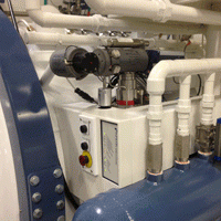
A residual gas analyzer or RGA for short is a compact mass spectrometer, designed for use either in the laboratory or out on the shop floor. These devices are often mounted for in-situ use on a vacuum furnace. RGA’s are typically designed for process control and contamination monitoring in vacuum systems.

Applications for residual gas analyzers include distinguishing leaks from outgassing, fingerprinting the process background, detecting helium and determining the effectiveness of gas line purging. A typical RGA gas analysis can reveal how much of a particular species is present either in the vacuum vessel or in the pump manifold. RGAs are used in most cases to monitor the quality of the vacuum and easily detect minute traces of impurities in the low-pressure gas environment. These impurities can be measured down to 10-14 Torr levels, possessing sub-ppm detectability in the absence of background interferences. RGAs can also be used as sensitive in-situ, helium leak detectors. With vacuum systems pumped down to lower than 10-5 Torr for checking of the integrity of the vacuum seals and the quality of the vacuum to detect air leaks, virtual leaks and other contaminants at low levels before a process is initiated.

Using Thermal Spray for Repair of Service-Damaged Parts

March 25, 2014 by VAC AERO International

Using Thermal Spray for Repair of Service-Damaged Parts

Thermal spray processes like air plasma spray and High-Velocity Oxygen Fuel (HVOF) are usually thought of as being used primarily for applying protective coatings to new parts. While new part applications do indeed constitute the majority of their use, there are also a wide variety of repair techniques that employ thermal spray processes. VAC AERO has been a leader in developing repairs for aircraft structural components and gas turbine engine parts using thermal spray processes. An example of a structural component repair involves a flap track from a popular turboprop aircraft.  As the wing flaps of this aircraft are extended and retracted during landing and take-off, rollers run along the surfaces of a series of components known as flap tracks.

An example of a structural component repair involves a flap track from a popular turboprop aircraft.  As the wing flaps of this aircraft are extended and retracted during landing and take-off, rollers run along the surfaces of a series of components known as flap tracks.  For the original flap track design, the manufacturer applied a nickel-based electroplated coating to protect the roller wear surfaces. However, after a certain period of service, the electro-plated coating was worn away and significant wear also occurred in the base metal substrate beneath. VAC AERO was tasked with coming up with a method of re-building the worn substrate and applying a more durable coating to the wear surfaces. VAC AERO’s solution was to use the HVOF process to apply a tungsten carbide coating over the worn area.  This coating was used for both the restoration of the damaged substrate and as a wear resistant overlay. Because this application requires high bond strength and fatigue resistance, several coating compositions were tested before the ideal candidate emerged. The development of the proper spray parameters also required significant effort to ensure the coating adhered properly, particularly where it “feathered” out at the edges of the overlay.  VAC AERO’s repair technique was subsequently approved by the aircraft manufacturer.

Influence of the Equations Defining HV and HK on Precision

March 9, 2014 by George Vander Voort

Influence of the Equations Defining HV and HK on Precision

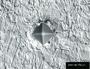
The basic equations defining (see equations 1 and 2) the Knoop (HK) and Vickers (HV) hardness, where the applied force is multiplied by a geometric constant and then divided by the long diagonal squared or the mean diagonal squared, respectively, cause an inherent problem in measuring small indents, that is diagonals ≤20 µm in length.  Figure 1 shows the calculated relationship between the diagonal and load and the resulting hardness for Knoop indents while Figure 2 shows this relationship for Vickers indents. As the test load decreases, and the hardness rises, the slope of the curves for diagonal versus hardness becomes nearly vertical. Hence, in this region, small variations in diagonal measurements will result in large hardness variations.

If we assume that the repeatability of the diagonal measurement by the average user is about ±0.5 µm, which is quite reasonable, and we add and subtract this value from the long diagonal length or the mean diagonal length, we can then calculate two hardness values. The difference between these values is ΔHK and ΔHV, shown in Figures 3 and 4. From these two figures, we can see how the steepness of the slopes shown in Figures 1 and 2 will affect the possible range of obtainable hardness values as a function of the diagonal length and test force for a relatively small measurement imprecision, ±0.5 µm. These figures show that the problem is greater for the Vickers indenter than for the Knoop indenter for the same diagonal length and test force. For the same specimen and the same test force, the long diagonal of the Knoop indent is 2.7 times greater than the mean of the Vickers’ diagonals, as shown in Figure 5.

Buying a Vacuum Furnace: New versus Used

February 25, 2014 by VAC AERO International

Buying a Vacuum Furnace: New versus Used

The purchase of a vacuum furnace involves a considerable capital investment.  As a result, the question of buying a used furnace at a lower cost than a new furnace is a fairly common one.  However, there are a number of potential issues with used equipment that should underscore the warning “buyer beware”. To begin with, good used vacuum furnaces are a rare commodity.  When they do appear on the market, they don’t last long.  Many of the best are purchased through industry networking and never reach the general market.  Still, there are numerous dealers of used furnace equipment with inventories posted on their websites.

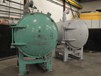
Most used furnaces are sold on an as-is, where-is basis with no manufacturer’s warranty.  If a decent used candidate is located, there are a few very important items to investigate before purchasing.  One of the biggest and most difficult to detect problems with used furnaces is the condition of the water jacket in the vacuum chamber.  The life of a properly maintained vacuum chamber can be well over twenty years.  However, in situations where the furnace cooling system has been connected to an untreated water supply, water jacket blockages from mineral build-up can begin to appear in as little as three years.  Beyond dissecting the vacuum chamber, there are no fool-proof methods for detecting blockages.  Ultrasonic testing is sometimes used but can be expensive and unreliable.  The presence of blistered or discolored paint on the outside of the chamber is a good indication of hot spots due to blockage.  Perhaps the best approach is to avoid altogether used furnaces more than twenty years old.  If water jacket blockage problems arise after purchase, the only sure solution is re-lining the chamber at considerable time and expense. BY JEFF PRITCHARD

Propeller Shaft of the USS Monitor

February 10, 2014 by George Vander Voort

Propeller Shaft of the USS Monitor

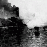
March 9, 1862 marks the date when the USS Monitor and the CSS Virginia (formerly the USS Merrimack) fought an indecisive naval battle at Hampton Roads that changed naval warfare from wood and sails to iron and steam. The USS Monitor sunk off the Outer Banks of North Carolina during a storm on December 31, 1862 but its remains were discovered in 1973. The wreck site, the Monitor National Marine Sanctuary, is managed by the National Oceanic and Atmospheric Administration (NOAA).

The Confederates began construction of an “ironclad” ship at the Gosport Yard of Hampton Roads in 1861. This was well known to the Union Navy Department. The US Army had actually launched ironclad gunboats in the summer of 1861 to patrol the Mississippi River; but none were available in the east to counter the Virginia. On August 3, 1861, Gideon Wells (Secretary of the Navy) requested design proposals for ironclad warships. Swedish inventor John Ericsson had designed an ironclad in 1854 for Napoleon III that incorporated a revolving cupola turret. Cornelius Bushnell promoted this design to Abraham Lincoln.

Loading of Parts in Vacuum Furnaces

February 9, 2014 by VAC AERO International

Loading of Parts in Vacuum Furnaces

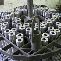
Component parts come in all shapes and sizes. To meet this demand vacuum furnaces have been designed to accommodate many standard workload configurations. Despite the almost limitless choices, some common sense rules apply. It is important to recognize that loading arrangements generally fall into two classes: weight limited and volume limited. In either case, when loading parts in furnace baskets or onto racks the goal is often to maximize loading efficiency. One must also be concerned with proper part spacing, that is, how parts are situated within the load for optimal heat transfer (e.g. line of sight heating), support and stability of the load at temperature, temperature uniformity, and heat extraction during quenching so as to achieve the desired metallurgical properties and minimize distortion.

How parts are loaded is very much a function of the geometry of the part as well as the style of the furnace being used. The most common arrangement used in horizontal vacuum furnaces is rectangular baskets designed for stacking or nesting (Fig.1) below. These are typically placed atop carrier grids. Semi-continuous furnaces utilize similar loading arrangements below or have parts placed directly onto the carrier grid. Vertical furnaces use fixtures to orient parts in an upright configuration below.  Cylindrical baskets can also be used. Loading orientation is very important when trying to minimize distortion in heat treatment. For loading parts in baskets, one can consider individual parts as occupying a cylindrical space that encompasses both the part and a separation space or “gap” between it and adjacent parts (Table 2).

Abradable Coatings used for Gas Path Seals in Turbine Engines

January 25, 2014 by VAC AERO International

Abradable Coatings used for Gas Path Seals in Turbine Engines

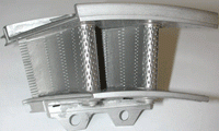
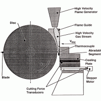
For maximum fuel efficiency, many gas turbine engine designs depend on sacrificial coatings to tighten internal clearances between moving parts. An extra gap of .005″ between the rotating blades and the engine casing can increase fuel consumption by as much as 0.5%. As fuel comprises more than half of direct operating costs, this waste can be significant. Engine efficiency largely depends on close clearance between blades and casing. Clearance can be affected by a number of engine operating variables, including casing expansion and contraction, loading due to maneuvering, thrust, gust, stall, vibration and manufacturing tolerances. An industrial turbine engine manufacturer (“OEM”) was experiencing unsatisfactory results with the ring segment coatings used to maintain rotor-shroud clearance. Because of poor abradability, the coatings cause excessive wear on the tips of the turbine blades. The OEM and VAC AERO agreed to work cooperatively to develop an improved abradable coating for these applications.

Materials normally used in sacrificial coatings for gas path seals include sintered metal-powder segments, sintered metal-fiber segments, metallic honeycomb (filled and unfilled), elastomers and thermally sprayed abradable coatings. Thermally sprayed coatings offer advantages over the other materials, including direct application, easy removal and repair, variety of coating materials and good performance. New abradable thermal spray coating materials have been proposed for performance in industrial turbine engines at operating temperatures up to 980°C.

An investigation of a variety of these new materials was under taken in order to quantify their performance during cyclic oxidation burner rig testing, hot corrosion burner rig testing and hot abradability rig testing as compared to existing abradable coating technology. Based on the results of these tests it was concluded that a significantly improved coating for abradable seals in industrial gas turbine engines was developed. This new coating can prevent excessive blade tip wear between 24,000-hour inspection intervals at operating temperatures up to 980°C. The successful coating consists of a specially heat treated MCrAIY bond coat, applied by HVOF, covered with a proprietary abradable top coat, applied by air plasma spray. By Jeff Pritchard, Scott Rush and A. Kiela

  • « Previous Page
  • 1
  • …
  • 16
  • 17
  • 18
  • 19
  • 20
  • …
  • 34
  • Next Page »
  • Vacuum Heat Treating: Education & Training
    • News & Announcements
  • Vacuum Technology with The Heat Treat Doctor
  • Vacuum Pump Technology: Education & Training
  • Metallography with George Vander Voort
  • Q’s and A’s
  • “What’s Hot!” Newsletter
  • Glossary Metallurgical Terms
Vertical vacuum furnace specifications
horizontal vacuum furnace specifications
Vacuum Furnaces
Vacuum Furnace Zone Rebuilds
Technical Articles and Resources

Specialists in Vacuum Furnace Technology - High Quality Vacuum Furnace Manufacturer

COMPANY

  • VAC AERO Products & Services
  • Company History
  • Certificates & Approvals
  • Employment Opportunities
  • Values & Commitment
  • Corporate Sponsorship
  • Corporate Brochure
  • Terms & Conditions of Use
  • Privacy Policy

FURNACE MANUFACTURING

  • Horizontal Furnace Specs
  • Vertical Furnace Specs
  • Hot Zones
  • Control Systems
  • Custom Vacuum Furnaces
  • Quality Control
  • Service & Support
  • Furnace Request For Quote (RFQ) Form

THERMAL PROCESSING

  • Ontario – Plant 1
  • Ontario – Plant 2
  • Quebec – Thermal Processing Division
  • Specific Heat Treating & Brazing Approvals
  • Metallurgical Services Matrix

COATINGS

  • Quebec Coatings Division
  • HVOF Spray System
  • Specific Coating Approvals
  • Metallurgical Services Matrix

SERVICES & SUPPORT

  • Furnace Rebuilds & Upgrades
  • Hot Zone Rebuilds
  • Process Controls Upgrades
  • Ordering Parts
  • Field Service
  • Training Seminars

© Copyright 2016 VAC AERO - All rights reserved. Site Map Contact Terms and Conditions Privacy